Determination of characteristics of material

a technology of characteristics and material, applied in the direction of optical detection, sorting, separation devices, etc., can solve the problems of difficult automatic identification, difficult camera-based recognition, and normal physical shape distortion, and achieve the effect of ensuring more lift than til

Inactive Publication Date: 2000-05-09
TITECH VISIONSORT +1
View PDF12 Cites 149 Cited by
  • Summary
  • Abstract
  • Description
  • Claims
  • Application Information

AI Technical Summary

Benefits of technology

For food quality control, the apparatus measures the quality of foodstuff by monitoring the absorption spectrum in the IR range. Fat content and maturing of fish, and the maturing of meat is today measured by single detectors only capable of single point measurements. Only the low range of the IR spectrum (<1 micron) is currently used, restricting the available information. The present apparatus enables much wider analysis in the IR spectrum, and also enables an almost continuous total quality control.
In separating beverage cartons from a stream of waste, the signals from each of the wavelength bands are combined using signal processing for each detection. The two-dimensional simulation which is built up as the stream passes the detection sta

Problems solved by technology

To make a positive identification by automatic means is very difficult.
Physical shape is normally quite distorted, making any camera-based recognition very complex unless the printing pattern is made in a specially

Method used


Image

  • Determination of characteristics of material
  • Determination of characteristics of material
  • Determination of characteristics of material

Examples


Embodiment Construction

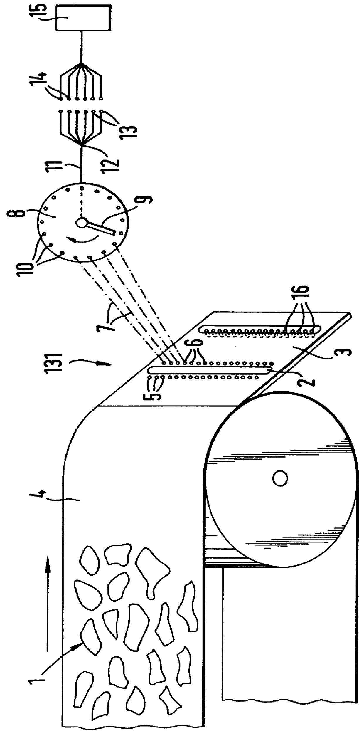
Referring to FIG. 1, at a detection station 131 there are 24 detection points across and below a single-layer stream 1 of waste objects as it passes over a transverse slot 2 formed through a downwardly inclined plate 3 at the downstream end of a continuously advancing conveyor belt 4, with a separate IR source 5 for each detection point. At each detection point the reflected IR passes through a lens 6 focussed into an optical fibre 7 and these optical fibres 7 are terminated at a scanner 8, where an arm 9 of a material transparent to IR scans the 24 terminal points 10 of the optical fibres. The plastics arm 9 could be replaced by a mirror system or an IR-conducting fibre. The output 11 of the arm 9 is on the axis of the scanner 8, where a diffuser 12 shines the IR onto 6 infrared filters 13 which pass only respective individual IR wavelengths to IR detectors 14 dedicated to respective wavelengths and connected to an electronic control device 15. In this way each detector 14 serves 2...


PUM


Abstract

A system for automatically inspecting matter for varying composition comprises one or more detection stations through which one or more streams of matter are advanced and particular materials therein are detected through their diffusely reflected IR spectra, if any, and/or through their variation of an electromagnetic field by their metallic portions, if any. A row of light sources distributed across the overall width of one or more belt conveyors may cause desired portions of the stream to reflect light diffusely onto a part-toroidal mirror extending over that overall width, whence the light is reflected, by a rotating, polygonal mirror through optical filters dedicated to differing IR wavelengths, onto detectors the data output of which is utilized in controlling solenoid valves operating air jet nozzles which separate-out the desired portions. Alternatively or additionally, an oscillator and an antenna which extends over that overall width generate an electromagnetic field through the belt and sensing coils sense variations therein produced by metallic portions of the stream passing through the detection station and the detection data produced by the sensing coils is used to control the solenoid valves operating the nozzles to separate-out the metallic portions.

Description

CROSS-REFERENCES TO RELATED APPLICATIONSNot applicable.STATEMENT REGARDING FEDERALLY SPONSORED RESEARCH AND DEVELOPMENTNot applicable.BACKGROUND OF THE INVENTION1. Field of the InventionThis invention relates to determination in first and second dimensions of characteristics of material, for example automatic inspection and sorting of discrete objects of differing compositions, e.g. waste objects, or automatic inspection of sheet material, which may be in the form of a strip, for surface layer composition, e.g. surface layer thickness.2. Description of Related ArtWith the recent focus on collection and recycling of waste, the cost effectiveness of waste sorting has become an essential economic parameter.In the "Dual System" in Germany all recyclable "non-biological" packaging waste excluding glass containers and newsprint is collected and sorted in more than 300 sorting plants.Objects can be sorted on the basis of:SizeDensity / weightMetal content (using eddy current effect)Ferrous me...

Claims


Application Information

Patent Timeline
IPC IPC(8): B07C5/342B07C5/344B07C5/34B07C5/36G01V8/20B07C5/346B09B5/00G01N21/35G01N21/84
CPCB07C5/342B07C5/3425B07C5/36B07C5/368B07C5/344Y10S209/938B07C2501/0054B07C2501/0036
Inventor ULRICHSEN, BORRE BENGTMENDER, CLAS FREDRIKFOSS-PEDERSEN, GEIRTSCHUDI, JON HENRIKJOHANSEN, IB-RUNE
Owner TITECH VISIONSORT
Why Eureka
Try Eureka