Liquid crystal display

a technology of liquid crystal display and display screen, applied in the field of liquid crystal display, can solve the problems of background art, display screen quality, and inability to be denied

Inactive Publication Date: 2000-05-16
AU OPTRONICS CORP
View PDF2 Cites 39 Cited by
  • Summary
  • Abstract
  • Description
  • Claims
  • Application Information

AI Technical Summary

Problems solved by technology

Since the degree of the afterimage made visible by the reflected light increases as Aperture ratio of the TFT type LCD increases, it is a problem from the viewpoint of the display screen quality.
However, the background art has the following problems.
However, it cannot be denied that the circuit design is made complicated by the provision of such circuit.
Further, as a larger essential problem, it is required to reserve a power supply for operating circuits such as a circuit for detecting the turn-off of the system power, or an afterimage removal power hold / supply circuit and a power turn-off request / enable circuit after the afterimage removal, which are needed in the above art, after the system power Vl is turned off.
However, circuit construction therefor is complex and expensive.

Method used


Image

  • Liquid crystal display
  • Liquid crystal display
  • Liquid crystal display

Examples


Embodiment Construction

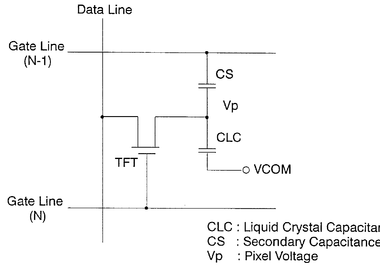
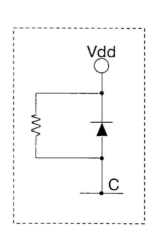
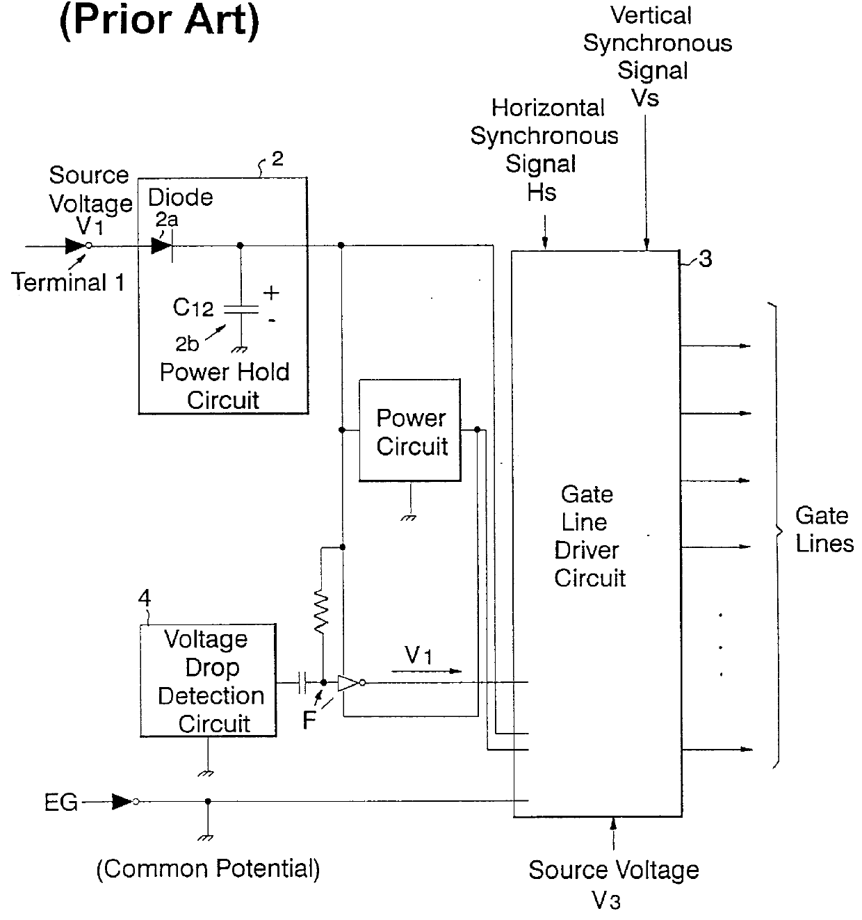
FIG. 3 is a schematic circuit diagram of the liquid crystal display in the present embodiment. In the TFT type LCD, many active switching elements 31 are arranged in a matrix. Each active switching element consists of an FET 31a and opposed pixel electrodes 31b. The gate of each FET 31a is connected to a gate line 32, and its source is connected to a source line, not shown. A gate line driver circuit 33 is to selectively select desired gate lines, and to the selected gate lines, a gate high voltage Vgh, a third source voltage, is supplied. And, to all the other gate lines which are not selected (unselected gate lines), a gate low voltage Vgl, a second source voltage, is supplied. A voltage generation circuit 34 is to generate various voltages such as the gate high voltage Vgh (e.g. +20 V) and the gate low voltage Vgl (e.g. -10 V) if the external power supplied to the liquid crystal display is a single source voltage Vdd (e.g. +5 V).

If the source voltage Vdd is supplied to the liquid...


PUM

PropertyMeasurementUnit
voltageaaaaaaaaaa
voltageaaaaaaaaaa
voltage Vglaaaaaaaaaa

Abstract

An afterimage occurring on a liquid crystal display is eliminated at the time of turning off the system power with an inexpensive circuit construction, without the need for reserving a special power supply. The afterimage continues to be displayed for a certain period of time after the turning-off of the power supply, and is eliminated by the load capacitance processed by liquid crystal display elements in a liquid crystal display panel.

Description

1. Technical FieldThe present invention relates to a liquid crystal display, in which an afterimage continued to be displayed for a certain time after the turning-off of the power is removed by the load capacitance possessed by liquid crystal display elements in a liquid crystal display panel.2. Prior ArtA TFT type LCD having active switching elements has a structure in which many active switching elements are arranged in a matrix. FIG. 1 shows an equivalent circuit of such TFT. One end of the TFT is connected to a data line, and the other end is connected to a pixel voltage terminal Vp. And, its gate is connected to a gate line N, and the TFT is selectively turned on / off in response to the signal provided to the gate line N. Further, the pixel voltage terminal Vp is connected to a voltage terminal VCOM through a liquid crystal capacitance CLC and connected to a gate line N-1 through a secondary capacitance CS.Generally, the output from a driver circuit for driving such panel is int...

Claims


Application Information

Patent Timeline
Patent Type & Authority Patents(United States)
IPC IPC(8): G09G3/36G02F1/133
CPCG09G3/3648G09G3/3696G09G2330/02G09G2310/0245
Inventor SAKAEDANI, TETSUYAAMEMIYA, TAKAHISASUZUKI, MIDORI
Owner AU OPTRONICS CORP
Why Eureka
Try Eureka