This helps you quickly interpret patents by identifying the three key elements:
Problems solved by technology
Method used
Benefits of technology
Benefits of technology
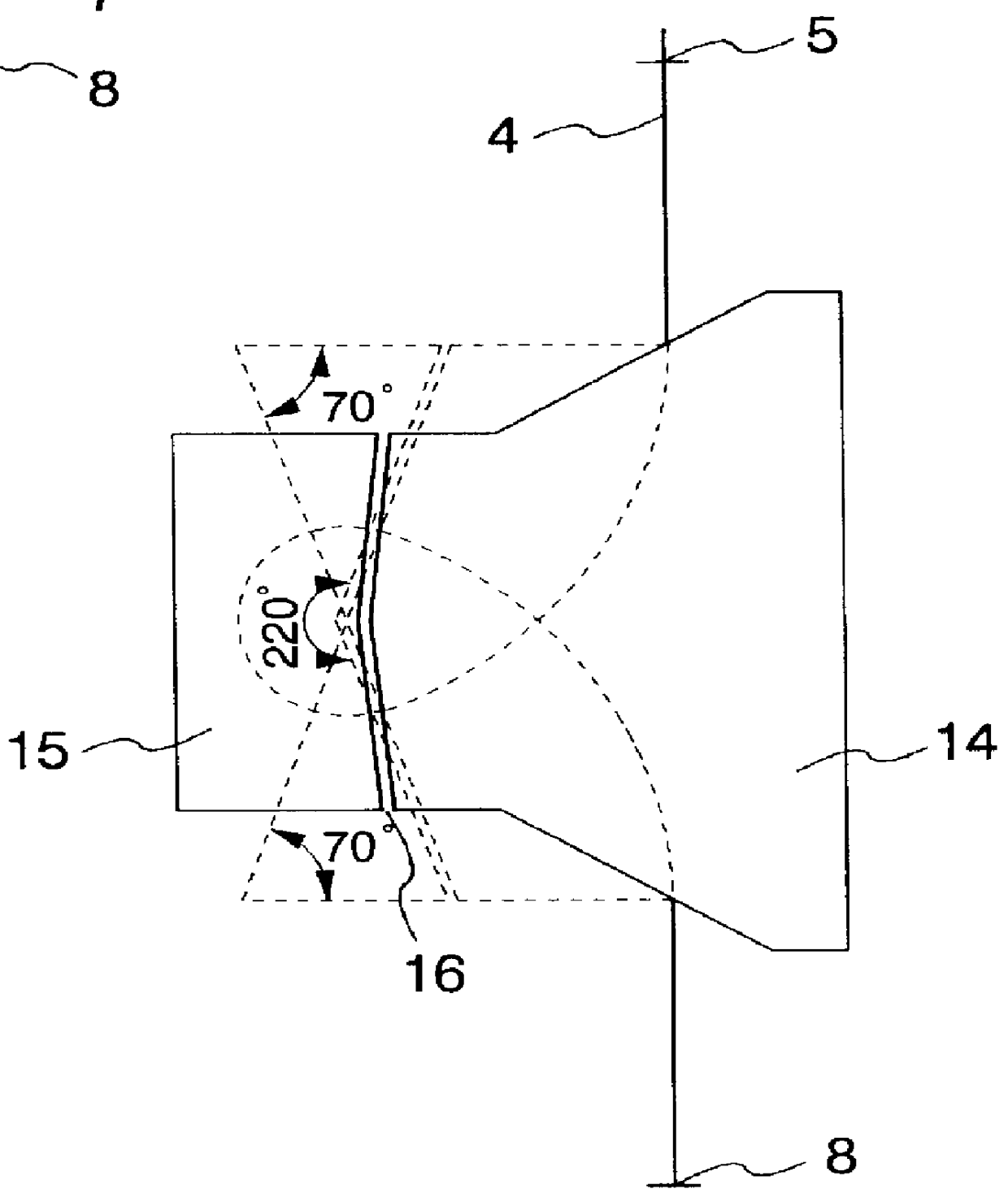
The electron energy filter is required to form an energy dispersion surface and an image surface with a small aberration. That is, the electrons 4 transmitted through the specimen enter at the crossover point 5 formed on a lens into the electron energy filter, pass through the filter and reach the energy dispersion surface 8 where the electrons having the specific energy are converged in the same direction though the electrons having the other energy are dispersed. On the energy dispersion surface 8, hence, the aberration has to be eliminated in order to restrict a lower resolution of the electrons passing through a slit. Moreover, the image formed on an inlet image surface 6 before the electron energy filter is required to be similarly formed on an outlet image surface point 7. Hence, the aberration has to be reduced to a minimum for suppressing the distortion of the image as much as possible.
It is an object of the present invention to provide an electron energy filter that is designed compactly with a small number of magnetic poles and offers a more excellent convergence characteristic.
Problems solved by technology
The electron optical system of the aforementioned conventional electron energy filter does not make sufficient allowance for the effect of the end magnetic field.
As mentioned below, the electron optical system does not completely meet these conditions.
Method used
Image
Click on the blue label to locate the original text in one second.
Reading with bidirectional positioning of images and text.
Examples
first embodiment
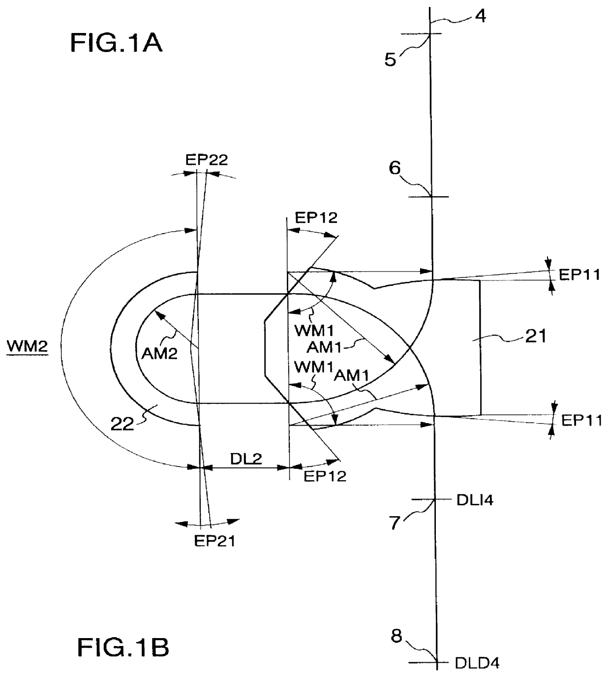
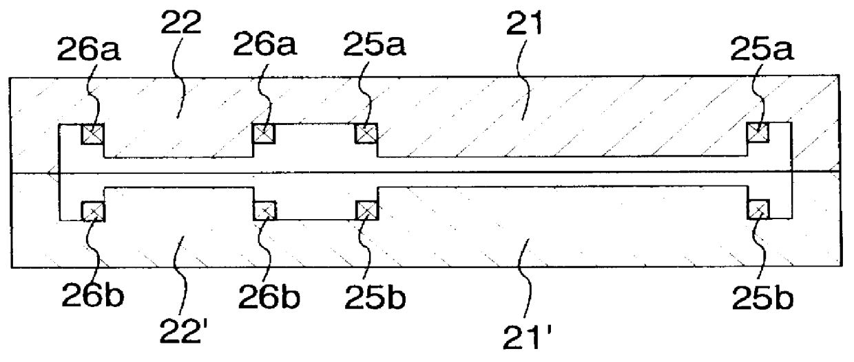
FIG. 1 is a schematic view showing the magnetic poles of an electron energy filter according to an embodiment of the present invention, in which FIG. 1A is a plane view and FIG. 1B is a central section. An electron beam 4 is deflected through the effect of a first magnetic field generated between a pair of magnetic poles 21 and 21' by virtue of current flowing through coils 25a and 25b and a second magnetic field generated between a pair of magnetic poles 22 and 22' by virtue of current flowing through coils 26a and 26b. After the electron beam 4 is deflected about 90.degree. by virtue of the first magnetic filed yielded by the first pair of magnetic poles 21 and 21', the deflected beam 4 travels straight on a first path and enters into the second magnetic field yielded by the second pair of magnetic poles 22 and 22', in which the beam is deflected 180.degree. in the substantially same direction. Then, the beam travels on the second path in the free space, which is substantially par...
second embodiment
In order to meet the expressions (3) and (4), the deflecting angle WM1 and the central trace radius AM1 in the first magnetic field, the deflecting angle WM2 and the central trace radius AM2 in the second magnetic field, the distance DL2 from the outgoing point of the first magnetic field to the incident point of the second magnetic field are selected in the following numerical ranges.
In order to reduce the secondary aberration to a minimum, the first incident angle EP11 and the outgoing angle EP12 of the electron beam in the first magnetic field and the incident and outgoing angle EP21 of the electron beam in the second magnetic field are selected in the following numerical ranges.
20.noteq..ltoreq.EP11.ltoreq.30.degree. (21)
20.degree..ltoreq.EP12....
third embodiment
In order to meet the expressions (3) and (4), the deflecting angle WM1 and the central trace radius AM1 in the first magnetic field, the deflecting angle WM2 and the central trace radius AM2 in the second magnetic field, and a distance from the outgoing point of the first magnetic field to the incident point of the second magnetic field are selected in the following numerical ranges.
In order to reduce the secondary aberration to a minimum, the first incident angle EP11 and the outgoing angle EP12 of the electron beam in the first magnetic field and the incident and outgoing angle EP21 of the electron beam in the second magnetic field are selected in the following numerical range.
15.degree..ltoreq.EP11.ltoreq.15.degree. (32)
30.degree..ltoreq.EP12.lt...
PUM
Abstract
PCT No. PCT / JP95 / 01401 Sec. 371 Date Jan. 14, 1997 Sec. 102(e) Date Jan. 14, 1997 PCT Filed Jul. 14, 1995 PCT Pub. No. WO96 / 02935 PCT Pub. Date Feb. 1, 1996An electron energy filter includes a first pair of magnetic poles for generating a first deflecting magnetic field and a second pair of magnetic poles for generating a second deflecting magnetic field in the same direction as the first deflecting magnetic field. The incident electrons are deflected about 90 DEG with a trace radius of AM1 through the effect of the first deflecting magnetic field, passed through a free space having a distance DL2 that is about a half of the trace radius AM1 and then are incident to the second deflecting magnetic field. The electrons are deflected about 180 DEG with a trace radius AM2 that is about a half of the curvature radius AM1 and are passed through the free space DL2. Then, the electrons are incident to the first deflecting magnetic field again where those electrons are deflected about 90 DEG . The deflected electrons are traveled like a gamma trace so that those electrons outgo in the same direction as the incident one. This filter so designed is made compact and to have a smaller aberration.
Description
The present invention relates to an electronic energy filter which is arranged to separate only electrons having specific energy from an electron beam and form an image of those electrons.In a transmission electronmicroscope, electrons transmitted through a specimen suffer from energy loss that is peculiar to one or more elements composing the specimen. To overcome this shortcoming, the electrons transmitted through the specimen are passed through an energy filter for analyzing energy of those electrons, separating only the electrons suffering from the specific energy loss, and forming an image of the separated electrons. The formed image corresponds to a mapping image of one or more specific elements contained in the specimen. Further, the use of only the electrons having specific energy for forming an image allows the energy loss of the electrons caused by the thickness of the specimen to be restricted to only specific electrons. The resulting image has excellent contrast.For the...
Claims
Application Information
Patent Timeline
Application Date:The date an application was filed.
Publication Date:The date a patent or application was officially published.
First Publication Date:The earliest publication date of a patent with the same application number.
Issue Date:Publication date of the patent grant document.
PCT Entry Date:The Entry date of PCT National Phase.
Estimated Expiry Date:The statutory expiry date of a patent right according to the Patent Law, and it is the longest term of protection that the patent right can achieve without the termination of the patent right due to other reasons(Term extension factor has been taken into account ).
Invalid Date:Actual expiry date is based on effective date or publication date of legal transaction data of invalid patent.

