"Intelligent" glazing structures with additional control layers

Inactive Publication Date: 2000-06-06
REVEO
View PDF4 Cites 98 Cited by
  • Summary
  • Abstract
  • Description
  • Claims
  • Application Information

AI Technical Summary

Benefits of technology

The present invention provides an additional means of controlling light incident on a smart window, whereby light outside the bandwidth normally controlled by th

Problems solved by technology

Also, if an infra red reflecting film is required which is transparent in the visible region, higher order effects occur to produce unwanted reflected colors from the

Method used


Image

  • "Intelligent" glazing structures with additional control layers
  • "Intelligent" glazing structures with additional control layers
  • "Intelligent" glazing structures with additional control layers

Examples


Embodiment Construction

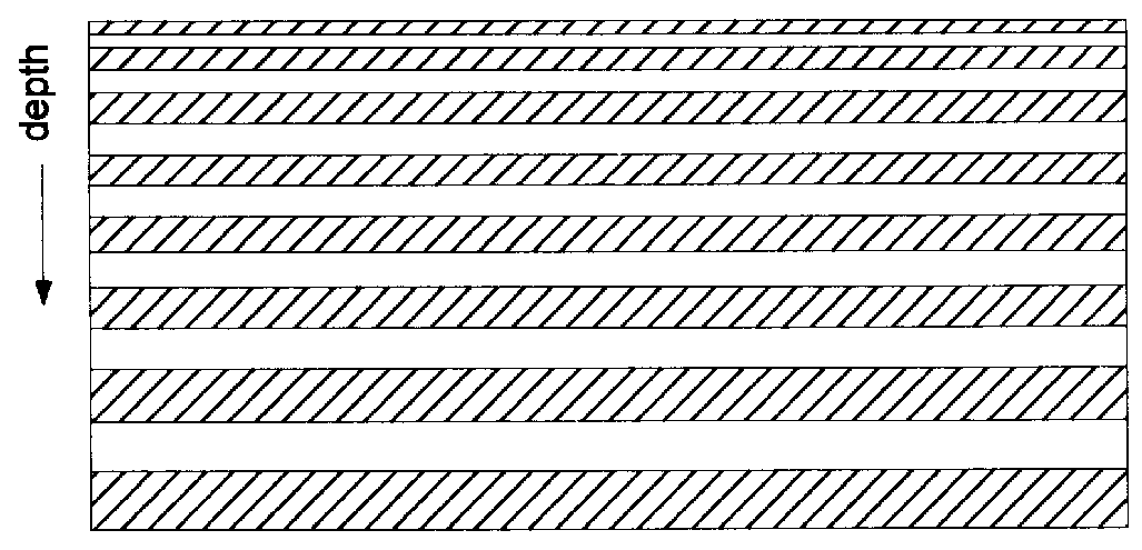
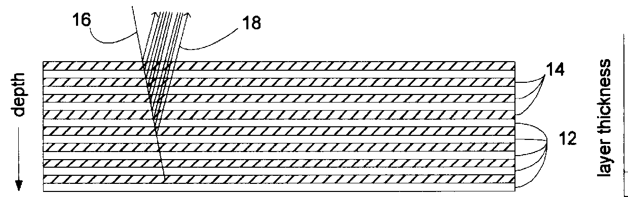
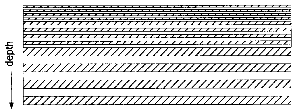
FIG. 1a shows a sketch of a prior art multilayer reflector film 10. Pairs of layers of two different transparent polymer materials 12 and 14 are arranged with each layer adjacent the next layer. Such films are generally co-extruded and pulled so that the thickness of the layers is in the submicrometer range. For a reflector, the layers shown in FIG. 1a are equal to one quarter of an optical wavelength (the wavelength of the light to be reflected divided by the index of refraction of the material for light of that wavelength). An incident light ray 16 is shown impinging on the film 10, and many reflections 18 are shown reflecting from the interface of the two transparent polymer materials 12 and 14. If the wavelength of the incident light 16 is correct, the reflections from the material interfaces add coherently to give high reflection. The "wavelength" of designed reflectivity is usually designed for light incident normally on to the film 10. FIG. 1a shows the light slightly off nor...


PUM

PropertyMeasurementUnit
Sizeaaaaaaaaaa
Electrochromicaaaaaaaaaa
Distributionaaaaaaaaaa

Abstract

An "intelligent" window combined with an additional structure for further controlling light incident on the "intelligent" window is disclosed.

Description

1. Field of InventionThe present invention relates generally to an electro-optical glazing structures ("smart windows") having reflection, semi-transparent, and transparent modes of operation which are electrically-switchable for use in dynamically controlling electromagnetic radiation flow in diverse applications and which have an additional layer to control incident light.2. Brief Description of the Prior ArtThe use of multilayer polymer films for controlling reflectivity has been known for many years. Such films comprise many layers, generally alternating between two types of transparent polymer, each having different refractive indices and an appropriate thickness related to the wavelength of the light to be controlled. U.S. Pat. No. 3,711,176, by Alfrey, Jr. et al. detailed theoretical details of such a film. U.S. Pat. No. 3,610,729, by Howard Rogers introduces a multilayer polarizer, where each alternate layer is birefringent, where the index of refraction for light of a first...

Claims


Application Information

Patent Timeline
IPC IPC(8): C09D11/16C09B67/00C09D11/02C09K19/00C09K19/52E06B9/24F24J2/40G01D11/28G02B27/00G02F1/13G02F1/1335G02F1/139G02F1/1347G02B5/30G02F1/1334G02F1/137G02F1/13357
CPCB82Y15/00C09D11/037C09D11/17C09K19/00C09K19/52E06B9/24F24J2/407G01D11/28G02B5/3016G02B27/0093G02F1/133514G02F1/13362G02F1/133621G02F1/13471G02F1/1393C09B67/0098Y02E10/40E06B2009/2464G02F1/1334G02F1/133536G02F1/13718G02F2001/133543G02F2001/133623H04N2213/008F24S50/80G02F1/133543G02F1/133623
Inventor FARIS, SADEGLI, LE
Owner REVEO
Why Eureka
Try Eureka