
Engine construction

Inactive Publication Date: 2000-06-13
CONTINENTAL MOTORS
View PDF8 Cites 20 Cited by
  • Summary
  • Abstract
  • Description
  • Claims
  • Application Information

AI Technical Summary

Benefits of technology

The engine of the present invention is constructed of a pair of mating half blocks each of which includes an integral cylinder head and which together form the engine block and the crankcase as well as a pair of oppositely positioned cylinder heads of the engine. The half blocks of the engine are joined by a plurality of spaced, quite long, through bolts which extend between the opposed cylinder heads and through the half blocks. The opposing cylinders of the engine are on the same centerline and this permits the through bolts to extend completely through the engine to tie the parts together. The through bolts provide for direct transfer of the cylinder firing forces from the cylinder heads to the main engine bearings. The transfer is accomplished in tension and compression with little bending for the most efficient use of material strength. The linking of the opposed cylinder heads by the long through bolts also provides a composite beam of exceptional stiffness for support of the engine main bearings and crankshaft. This stiffness is essential in providing even force distribution on the main and crank pin bearings to thereby promote bearing life.
The composite structure results in the firing pressure in the cylinders being transmitted through the steel cores to the through bolts and to the through bolt bosses between and beside the cylinders and thence through the matrix structures to the main bearings. This provides the necessary lightweight for an engine such as an aircraft engine without sacrificing power.

Problems solved by technology

Such engines however, have been quite heavy.

Method used


Image

  • Engine construction
  • Engine construction
  • Engine construction

Examples


Embodiment Construction

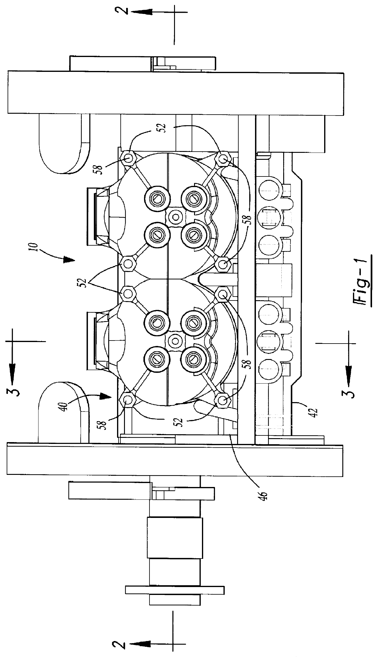
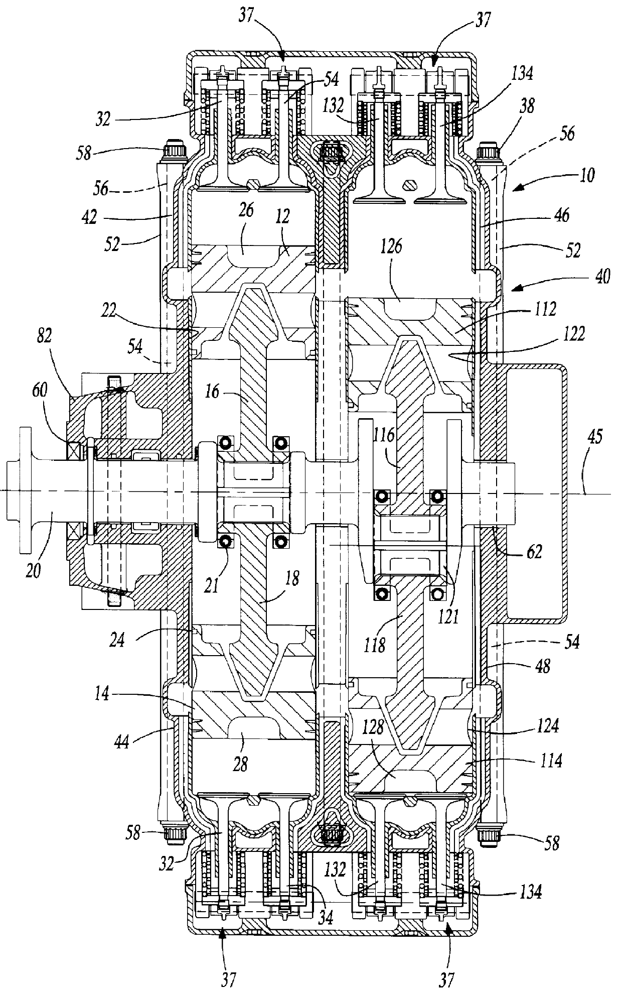
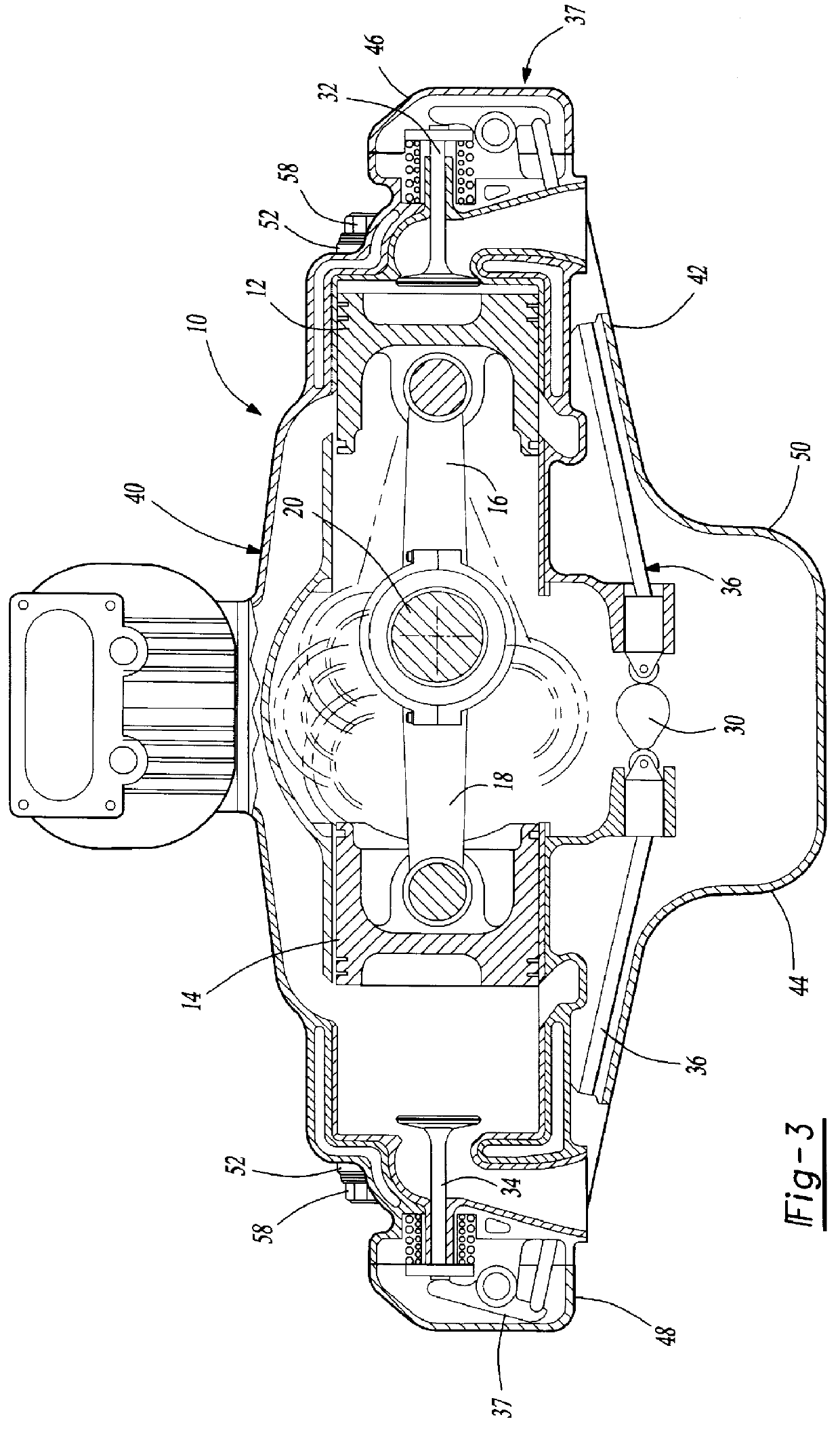
With reference to the drawings, a preferred embodiment of the present invention is illustrated as comprising an engine 10 having at least a pair of opposed pistons 12 and 14 connected by connecting rods 16 and 18 and bearings 21, respectively, to a crankshaft 20 between the pistons 12 and 14. The pistons 12 and 14 are connected to the crankshaft 20 by a bearing 21 and have their centerlines aligned.

As can best be seen in FIG. 2 the engine 10 of the preferred embodiment is a four cylinder engine so that a second set of pistons 112 and 114 is also connected to the crankshaft 20 but by connecting rods 116 and 118 respectively and bearings 121.

Still referring to FIG. 2 the pistons 12 and 14 move reciprocally within a pair of cylinders 22 and 24 respectively and the pistons 112 and 114 move reciprocally within cylinders 122 and 124 respectively in response to combustion in combustion chambers 26, 28 and 126, 128 formed in part in the top of the pistons 12, 14, 112, and 114 respectively.

A...


PUM


Abstract

An in-line opposed cylinder engine constructed of a pair of half blocks which when combined form a pair of spaced cylinder heads and an intermediate crankcase and in which the cylinder heads and the intermediate crankcase are tied together by a plurality of spaced elongated through bolts which extend through the cylinder heads and through the half blocks. Each cylinder head is integral with the remainder of the half block and is preferably of a composite construction with a core of steel or the like which forms the cylinder bore, the firing deck, the exhaust ports and the valve guide as well as the main bearing supports. A matrix structure of lighter material such as aluminum is cast around the core and forms the induction air passages to the intake ports, the coolant passages, oil passages, and the main bearing bosses.

Description

The present invention relates to internal combustion engines, and more particularly to a lightweight engine having directly opposed cylinders and such an engine especially suited for high pressure combustion such as a diesel engine.DESCRIPTION OF THE PRIOR ARTOpposed cylinder internal combustion engines are not new. U.S. Pat. No. 2,489,068 issued to Carlson, for instance, discloses such an engine. Such engines however, have been quite heavy. The present invention provides an opposed engine which has a lightweight construction making it especially suitable as the means for propelling lightweight general aircraft. Other patents which disclose opposed cylinder internal combustion engines include U.S. Pat. No. 1,639,334 issued Aug. 16, 1927 to Ford; U.S. Pat. No. 2,093,433 issued Sep. 21, 1937 to Greene; and U.S. Pat. No. 2,275,478 issued Mar. 10, 1942 to Taylor.None of these patents discloses an in-line opposed cylinder engine having the lightweight characteristics of the present inven...

Claims


Application Information

Patent Timeline
IPC IPC(8): F02B75/24F02B75/00F02B61/00F02B61/04
CPCF02B75/246F02B61/04
Inventor BROGDON, JAMES W.
Owner CONTINENTAL MOTORS
Learn More