Pivoting lever cam guide tape head positioner

a lever cam and tape head technology, applied in the direction of maintaining head carrier alignment, tracking following on tapes, instruments, etc., can solve the problems of limited number of tracks that could be defined on the tape storage medium, efforts have reached practical limits, and the prime cost of manufacturing is reduced, so as to ensure the stability of the tape over the useful life of the tape. , the effect of high mechanical rigidity and resistance to vibration

Inactive Publication Date: 2000-06-13
QUANTUM CORP
View PDF12 Cites 93 Cited by
  • Summary
  • Abstract
  • Description
  • Claims
  • Application Information

AI Technical Summary

Benefits of technology

Another object of the present invention is to provide a dual actuator positioner for a tape drive which manifests a high level of mechanical rigidity and resistance to vibration in a manner overcoming limitations and drawbacks of the prior art.
Yet another object of the present invention is to provide a dual actuator positioner for a tape drive which is simplified over prior designs, which may be realized

Problems solved by technology

However, while the known coarse positioner worked satisfactorily for tape track densities on the order of 256 tracks per inch, instantaneous lateral tape motion disturbances effectively limited the number of tracks that could be defined on the tape storage medium.
While these prior approaches have worked to enable increases in track densities, a limitation with open loop or quasi closed loop positioning remained, due to lateral tape motion caused by a number of vibration excitation sources, including the supply reel and motor, take-up reel and motor, and guide rollers which guide the tape along a predetermined tape path across the head structure.
While prior efforts to reduce causes of lateral tape motion have been successful, as track densities increase (meaning that track widths are decreased) these prior efforts have reached practical limits, and have necessitated use of close

Method used


Image

  • Pivoting lever cam guide tape head positioner
  • Pivoting lever cam guide tape head positioner
  • Pivoting lever cam guide tape head positioner

Examples


Embodiment Construction

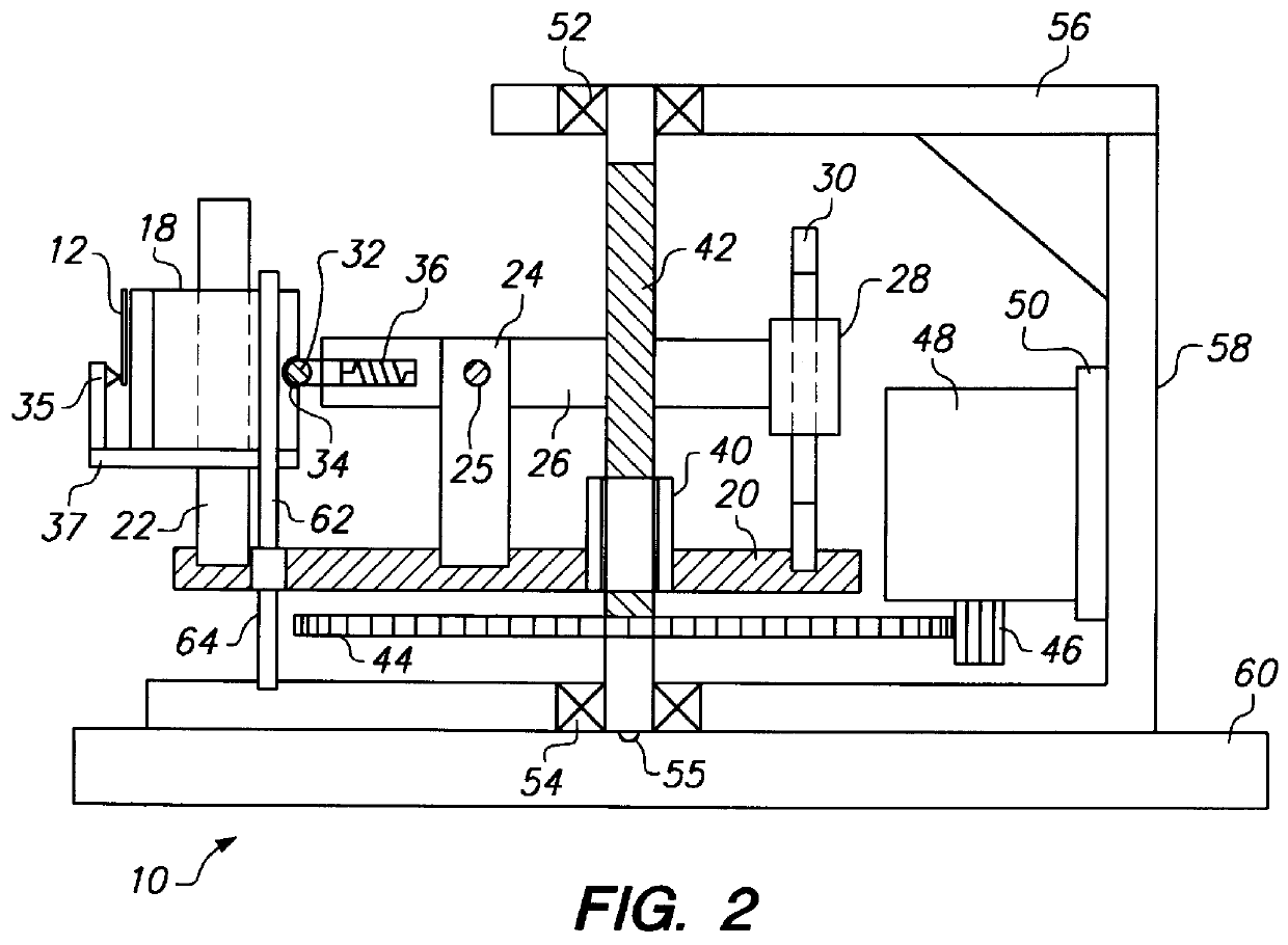
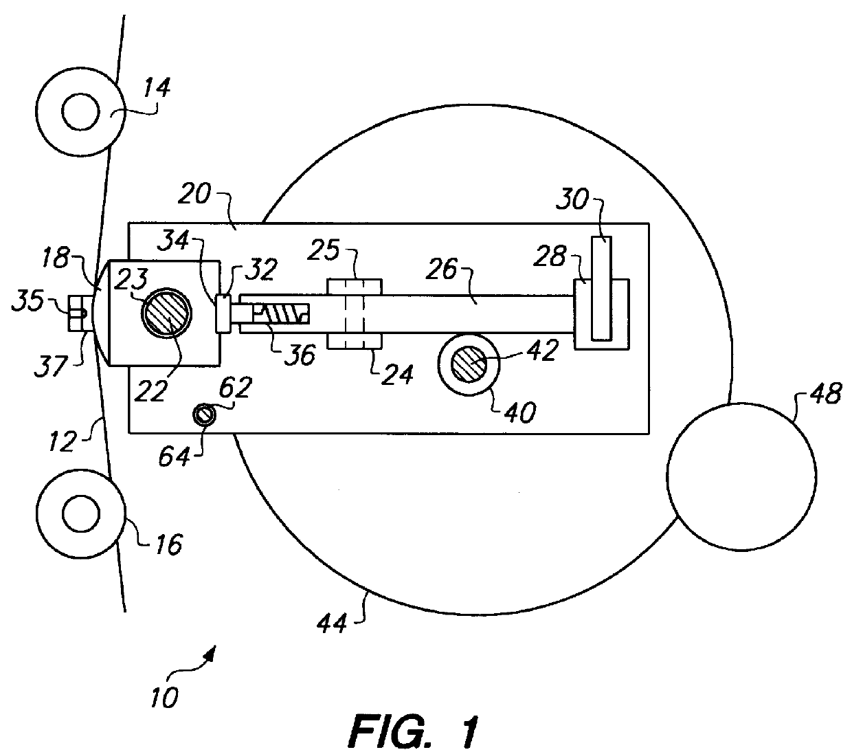
With reference to FIGS. 1 and 2 a tape transport 10 incorporating principles of the present invention includes a base 60 which supports and registers various structural and functional elements needed for effective tape transport, recording and playback. These elements typically include a supply tape reel holding a coil or pancake of magnetic recording tape, a small segment of which is marked by reference numeral 12 in FIG. 1, and a take-up tape reel, and associated reel motors (not shown in FIGS. 1 and 2 but present in a practical embodiment of the invention). The supply tape reel most preferably is contained within a single-reel tape cartridge and holds a supply, e.g. 1800 feet or more, of one half-inch magnetic recording tape. The single-reel tape cartridge is most preferably of the type marketed by the assignee of the present invention under the DLTtape (tm) brand of single reel linear streaming tape cartridges. Accordingly, the tape transport 10 includes a mechanism for receivin...


PUM


Abstract

A fine lateral head positioner for a tape drive includes a frame mounted to a base of a tape transport. A tape head slides laterally along a head guide. A guide beam actuated by a fine position actuator applies limited transverse adjustments to the tape head relative to a tape transport path via a cam and cam-follower arrangement. A coarse positioner between the frame and the base provides coarse position adjustment of the tape head laterally among multiple sets of parallel tracks defined along a longitudinal direction of a magnetic tape moving along the tape transport path, and the guide beam provides fine position adjustment of the tape head enabling it to follow in real time a particular set of parallel tracks of the tape during each data writing or reading operation.

Description

The present invention relates to tape recording and playback devices and subassemblies thereof. More particularly, the present invention relates to a tape head positioner subassembly having a pivoting lever cam guide for fine positioning a tape head transversely to a magnetic tape carrying multiple longitudinal recording tracks and head servo information.Tape recording systems employing multiple parallel longitudinal tracks recorded on e.g. one half inch tape are known. Each track typically extends for the entire useful length of the tape, which may be 1800 feet or longer. A head structure contains multiple read / write head elements. When user data is being recorded, a first set of tracks is recorded as the tape moves in a first or forward direction across the heads. When the end of the tape is reached, the head structure is repositioned, and a second set of tracks is recorded as the tape moves in a second or reverse direction across the heads. This back-and-forth recording process c...

Claims


Application Information

Patent Timeline
IPC IPC(8): G11B21/08G11B21/10G11B5/55G11B5/584
CPCG11B5/5504G11B21/103G11B21/088G11B5/584
Inventor SALIBA, GEORGE A.
Owner QUANTUM CORP
Why Eureka
Try Eureka