Telecommunications apparatus and plug-in unit for same

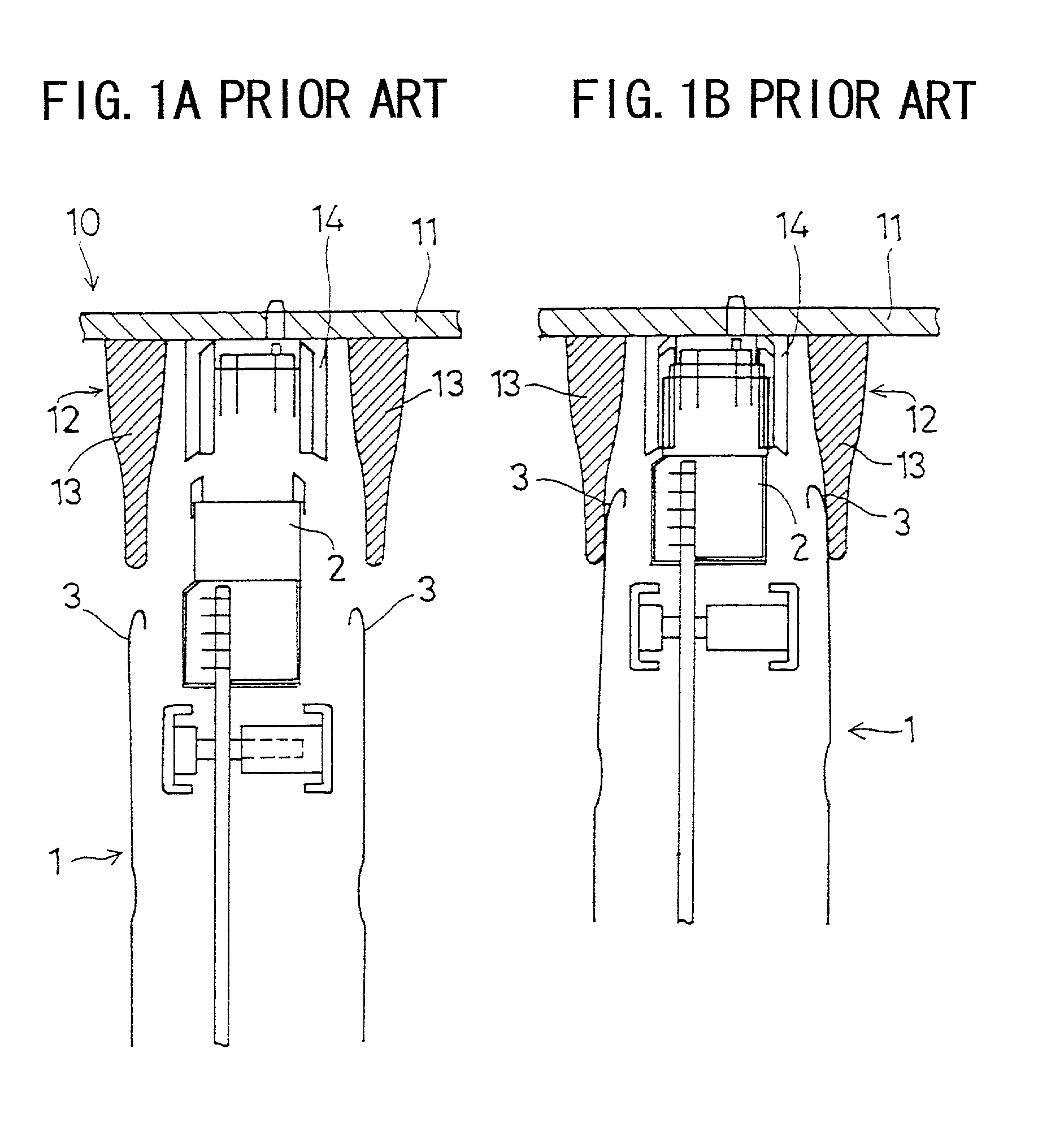
a technology for telecommunication equipment and plug-in units, applied in the field of telecommunication equipment, can solve the problems of lack of emc, exposed connectors, and unsuitable for the next generation of telecommunication equipmen

Inactive Publication Date: 2006-04-11
FUJITSU LTD
View PDF6 Cites 10 Cited by
  • Summary
  • Abstract
  • Description
  • Claims
  • Application Information

AI Technical Summary

Benefits of technology

[0037]According to this aspect of the invention, the cover part surrounds the plug-in unit connector and, further, the projection of the edge surfaces of the cover part beyond the edges of the plug-in unit connector protect the plug-in unit connector from damage if the plug-in unit is incorrectly inserted and dropped to the floor.

Problems solved by technology

This exposed connector thus lacks adequate EMC, and thus it is necessary to shield the insertion end of the plug-in unit when the plug-in unit is inserted in the subrack, that is, when the plug-in unit connector is connected to the back wiring board connector.
As a result, telecommunications equipment having the structure shown in FIGS. 1A and 1B is not capable of providing adequate EMC where the oscillators generate signals on the order of 40 GHz, and hence are not suitable for the next generation of telecommunications equipment.

Method used


Image

  • Telecommunications apparatus and plug-in unit for same
  • Telecommunications apparatus and plug-in unit for same
  • Telecommunications apparatus and plug-in unit for same

Examples


first embodiment

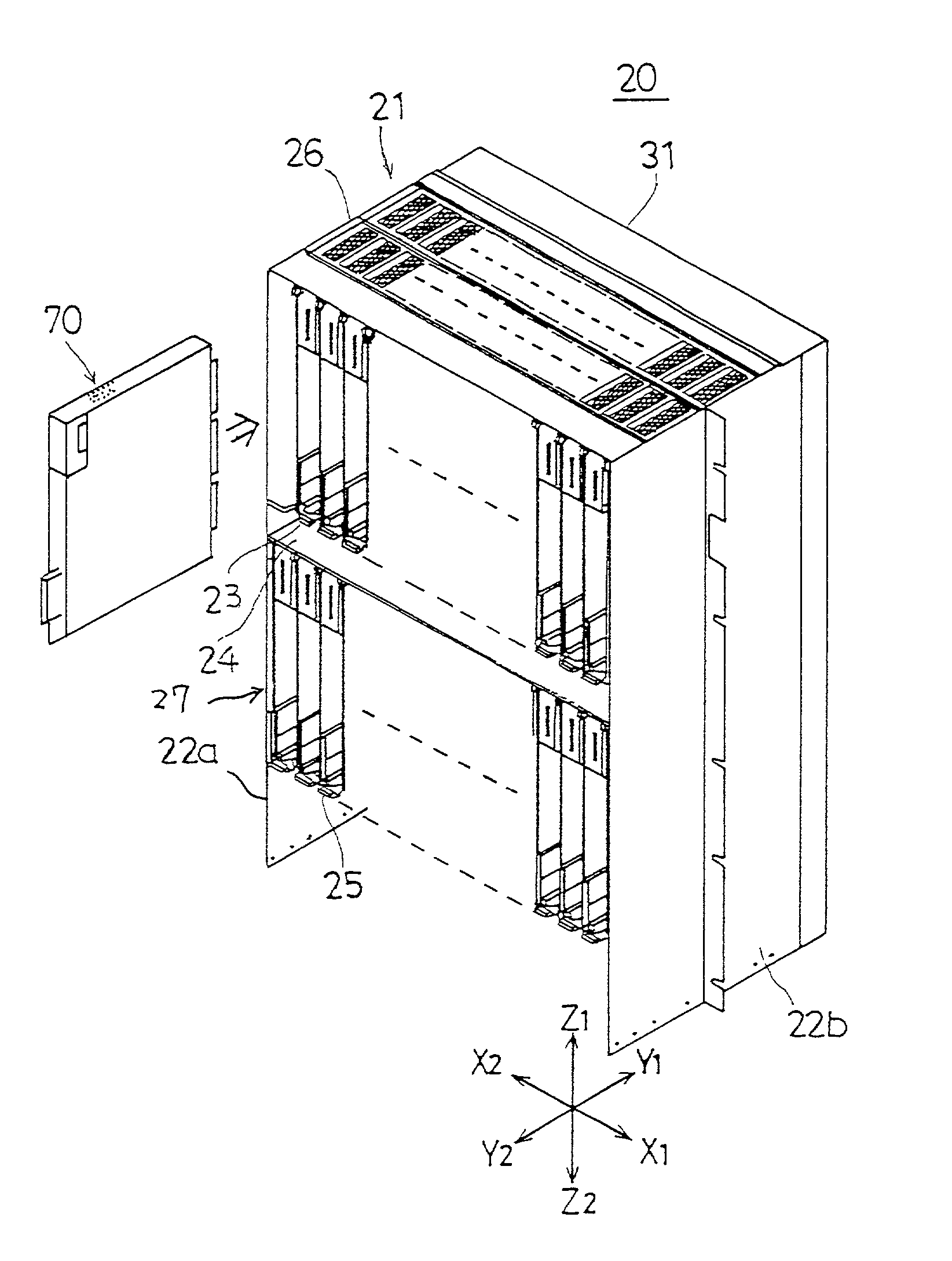
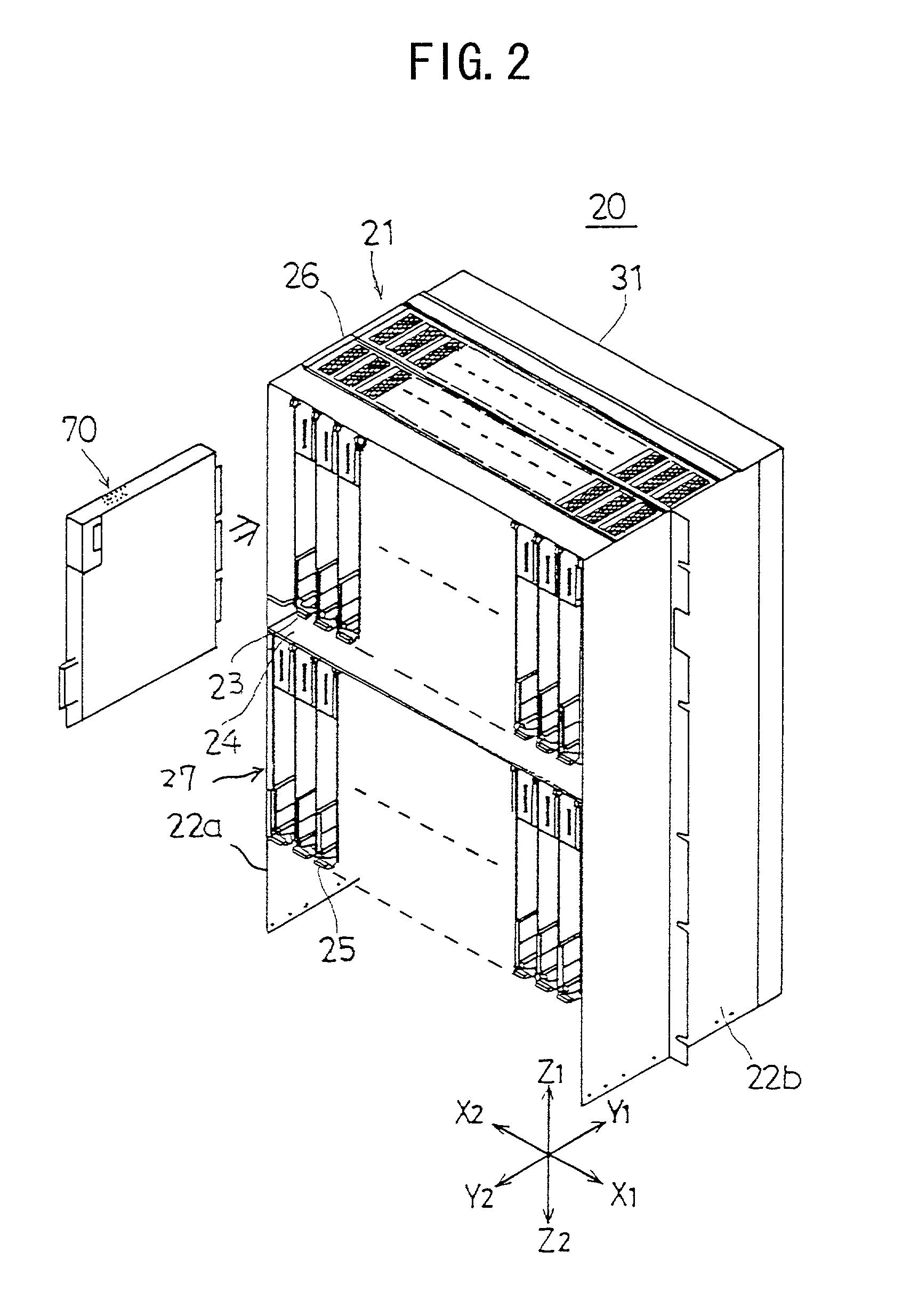
[0063]FIG. 2 is a diagram showing a perspective view of the telecommunications apparatus according to the present invention. FIG. 3 is an exploded perspective view of the subrack unit shown in FIG. 2. For convenience of description, a direction along an X axis denotes a direction in a width of a telecommunications apparatus 20, a direction along a Y axis denotes a direction in a depth of the telecommunications apparatus 20 and a direction along a Z axis denotes a direction in a height of the telecommunications apparatus 20.

[0064]As shown in the diagrams, the telecommunications apparatus 20 is configured so that a plurality of plug-in units 70 are inserted in a subrack 21, the plug-in units being inserted from the Y2 direction toward the Y1 direction and aligned horizontally in the Z1–Z2 direction and, further, divided into two shelves vertically in the Z1–Z2 direction. The particular telecommunications apparatus 20 depicted in the diagrams is forced-air cooled by an updraft created ...

second embodiment

[0122]A description will now be given of a telecommunications apparatus according to the present invention, with reference to the accompanying drawings.

[0123]FIG. 12 is a diagram showing a telecommunications apparatus according to a second embodiment of the present invention.

[0124]As shown in the diagram, the telecommunications apparatus 20A comprises a BWB 28, a frame member 29A, and a plug-in unit 70A.

[0125]The frame member 29A has the electrically conductive rubber flange 62 provided on a rear surface 45A. A front surface 44A is configured so that the main frame 40 is exposed.

[0126]The plug-in unit 70A is configured so that an oblong-shaped electrically conductive rubber flange 140 is positioned on a rear surface of an aluminum case 80A in such a way as to surround the connector 75, being attached thereto by an electrically conductive adhesive.

[0127]In a state in which it is mounted in the subrack 21, the plug-in unit 70A elastically deforms the electrically conductive rubber fla...

third embodiment

[0128]FIG. 13 is a diagram showing a telecommunications apparatus according to the present invention.

[0129]As shown in the diagram, the telecommunications apparatus 20B comprises the BWB 28 and a plug-in unit 70B, but no frame member.

[0130]The plug-in unit 70B is configured so that an oblong-shaped electrically conductive rubber flange 150 is positioned on a rear surface of an aluminum case 80B in such a way as to surround the connector 75, being attached thereto by an electrically conductive adhesive.

[0131]In a state in which it is mounted in the subrack 21, the plug-in unit 70B elastically deforms a tip part of the electrically conductive rubber flange 150 so as to cause the tip part of the flange 150 to contact the frame ground layer 32 of the front surface of the BWB 28, thus leaving or creating no gap. As a result, between the aluminum case 80B and the BWB 28 there exists fully adequate EMC.

[0132]It should be noted that the above-described coating 60 and flanges 61, 62, 63, 140...


PUM


Abstract

A telecommunications apparatus that has a substantially box-shaped subrack having a back wiring board mounting a connector and a plurality of shell-type plug-in units inserted in the subrack so that a connector of each of the plug-in units is connected to the connector of the subrack, further includes a flexible, electrically conductive seal member elastically deformedly disposed between a lateral surface of the plug-in unit inserted into the subrack and an interior portion of the subrack so as to enclose both the plug-in unit connector.

Description

BACKGROUND OF THE INVENTION[0001]1. Field of the Invention[0002]The present invention relates to a telecommunications apparatus, and more particularly, to a telecommunications apparatus of a type typically used in telecommunications stations to carry out high-speed telecommunications, in which a plurality of shell-type plug-in units are aligned inside a subrack which is mounted in a rack.[0003]2. Description of Related Art[0004]Together with the growing importance of telecommunications in recent years there is a growing need for improvements in the quality of the telecommunications equipment used in station buildings and the like. One such improvement in quality has to do with lowering the amount of electromagnetic interference (EMI) radiated from such equipment, as well as reducing the electromagnetic susceptibility (EMS) of such equipment to external EMI. Taken together, these measures are an index of the electromagnetic compatibility, or EMC, of the equipment.[0005]Additionally, ...

Claims


Application Information

Patent Timeline
Patent Type & Authority Patents(United States)
IPC IPC(8): H04M1/00H04M9/00H01R13/648H01R24/00H04B1/08H04B15/02H04Q1/10H05K7/14
CPCH04Q1/10H04Q1/116H05K7/1452H04Q1/035H04Q2201/02H04Q2201/12H04Q2201/14
Inventor MIYAZAKI, TAKEHIDEIINO, KAZUHIROYAMAZAKI, NAOYAHONGOH, TOMOYUKIHOSHINO, YOSHINORITADA, YOSHIAKI
Owner FUJITSU LTD
Why Eureka
Try Eureka