Optical recording medium having pits that are formed with respect to a wobbled groove at substantially constant positions in each cycle of the groove having a pit

a technology of optical recording medium and wobbled groove, which is applied in the direction of instruments, recording signal processing, disposition/mounting of heads, etc., can solve the problems of insufficient above-mentioned accuracy, obstruction of rotational control of discs, and inability to properly demodulate address information

Inactive Publication Date: 2000-06-13
SONY CORP +2
View PDF11 Cites 71 Cited by
  • Summary
  • Abstract
  • Description
  • Claims
  • Application Information

AI Technical Summary

Benefits of technology

With the above configuration of the present invention, the address information and the rotation control information for the optical recording medium can be obtained accurately despite narrow track pitch thus contributing to high density recording.
The response speed and reliability of rotational control of the optical recording medium may also be improved simultaneously. For example, if rotation of the CLV disc is controlled by only land pre-pits, these pre-pits cannot temporarily cannot be detected if the linear velocity is changed significantly due to random accessing, such that considerable time is consumed until the pre-pits are again detected to resume the rotational control. This inconvenience is resolved by using the wobbled pits and the pit signals simultaneously.
In addition, it is possible with the present invention to derive the address information more accurately and with high time precision than is possible with the conventional technique.
Moreover, if, with the optical recording medium of the present invention, the wobbled signal and the address signals are read by the sole beam spot, it becomes possible to detect the playback signal corresponding to the recording signal, servo a signals (focusing servo and tracking servo signal), wobbled signal and the address information in their entirety, thus simplifying the recording / reproducing apparatus and enabling the recording / reproducing apparatus to be manufactured at reduced cost.

Problems solved by technology

The address information not only cannot be demodulated correctly, but also the carrier wave of the wobbled signal, required for rotational control of the disc, becomes difficult to detect thus giving rise to obstructions in rotational control of the disc.
However, the above-mentioned accuracy is not sufficient.
For example, if rotation of the CLV disc is controlled by only land pre-pits, these pre-pits cannot temporarily cannot be detected if the linear velocity is changed significantly due to random accessing, such that considerable time is consumed until the pre-pits are again detected to resume the rotational control.

Method used


Image

  • Optical recording medium having pits that are formed with respect to a wobbled groove at substantially constant positions in each cycle of the groove having a pit
  • Optical recording medium having pits that are formed with respect to a wobbled groove at substantially constant positions in each cycle of the groove having a pit
  • Optical recording medium having pits that are formed with respect to a wobbled groove at substantially constant positions in each cycle of the groove having a pit

Examples


first embodiment

An optical disc of the present embodiment is a write-once type disc, 12 cm in diameter, having a recording film of an organic dye on which recording can be done using a laser beam having a wavelength of 635 nm.

The disc is formed of polycarbonate and is produced by injection molding with a guide groove and a land between neighboring turns of the guide groove.

The groove is approximately 0.25 .mu.m in width and approximately 70 nm in depth and is formed as a continuous spiral groove from the inner rim to the outer rim, with the groove interval or track pitch of approximately 0.74 .mu.m.

The wobbled signal of a sole frequency is recorded as the information for controlling the rpm of the disc and the clock frequency of the recording signal. The wobbling means slight meandering of the groove in the radial direction of the disc.

In the present embodiment, the meandering width is 20 nm and the meandering period is approximately 30 .mu.m. Therefore, if the disc is rotated at a linear velocity ...

second embodiment

In the present embodiment, various combinations of the wobbled pits are explained.

In a first example, wobbling of a sole frequency and pits having a integer number relation with respect to the frequency of the wobbled signal is explained.

The signal obtained in this case is as shown in FIG. 8, from which it is seen that pit signals Sp are detected at an interval equal to an integer times the period Tw of the wobbled signal Sw, that is at an interval equal to an integer times the pit period Tp.

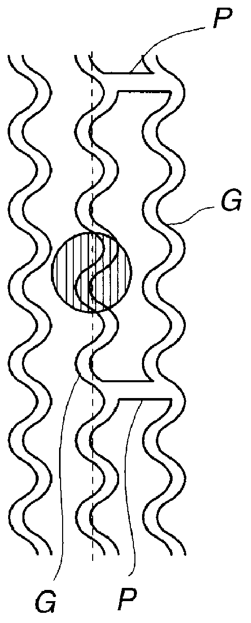
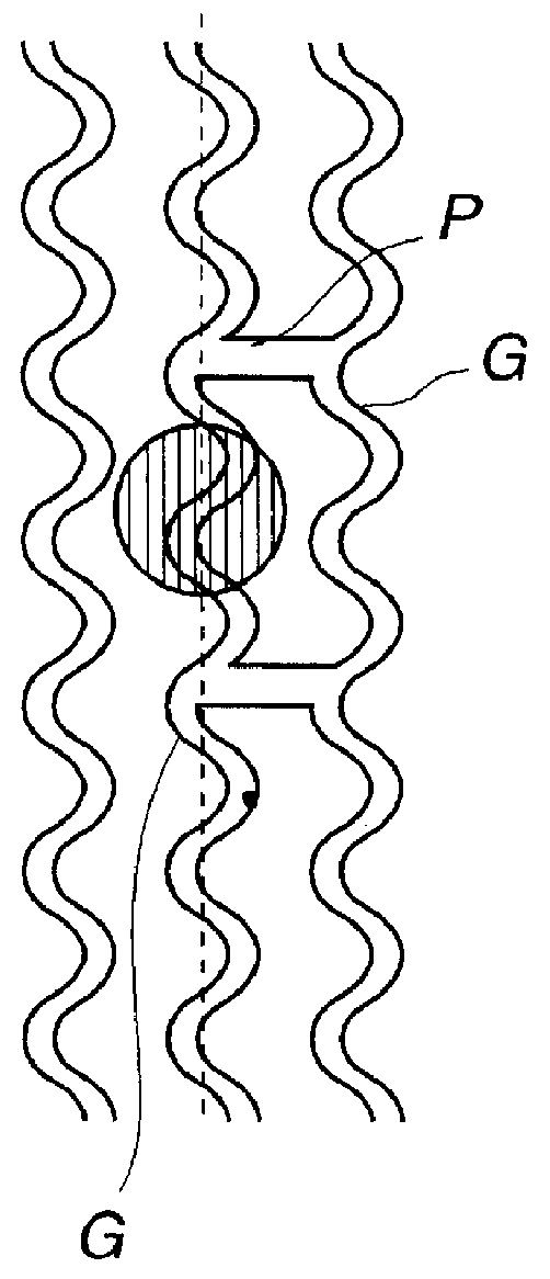
In a second example, pits are formed in phase with the modulated wobbled signal. In the present example, pits are formed at positions proximate to the neighboring groove, corresponding to the maximum wobbling. The pit signals Sp are positioned at apices of the wobbled signal Sw and pits are detected based only of the signal level of the pit signal Sp, as shown in FIG. 9.

In FIG. 9, the pit signal Sp is generated by the pit formed on the inner rim side of the groove during tracking. On the other h...


PUM

PropertyMeasurementUnit
wavelengthaaaaaaaaaa
wobbling frequencyaaaaaaaaaa
diameteraaaaaaaaaa

Abstract

An optical recording medium for accurately deriving the address information or the disc rotation control information despite narrow track pitch and for recording signals to a high density, and a method and apparatus for recording and / or reproducing such optical recording medium. The optical recording medium has a wobbled groove and pits formed at a pre-set interval in an area between turns of the wobbled groove. The recording / reproducing method includes controlling rotation of the optical recording medium by a wobbled signal from the groove and detecting the position on the optical recording medium of a recording signal by pit signals detected from the pits. The recording / reproducing apparatus includes a detection device for detecting the wobbled signal from the groove and a detection device for detecting pit signals from the pits. The rotation of the optical recording medium is controlled by the wobbled signals detected from the groove and the position on the optical recording medium of the recording signal is detected by the pit signal detected from the pits.

Description

1. Field of the InventionThis invention relates to an optical recording medium having a wobbled groove, more particularly, to a novel optical recording medium capable of recording signals to a high density. The invention also relates to a method and apparatus for recording and / or reproducing such optical recording medium.2. Description of the Related ArtThe CD-R disc, used in, for example, a so-called compact disc recordable system (CD-R), has a wobbled groove. The sector information, inclusive of the address information, is recorded by modulating the wobbled signal.Specifically, in a CD-R recording and / or reproducing apparatus, the wobbled signal having 22 kHz as carrier wave, is detected by a recording and / or reproducing light spot converged on the groove. A data string including the address information is detected by FM demodulating the wobbled signal.In a system in which the address is arrayed at the leading end of the sector, the address information and the recording informatio...

Claims


Application Information

Patent Timeline
Patent Type & Authority Patents(United States)
IPC IPC(8): G11B19/28G11B7/007G11B7/09G11B7/24G11B7/005G11B7/26
CPCG11B7/00736G11B7/00745G11B19/28G11B7/24082G11B7/24085G11B7/0938G11B7/0053G11B7/007G11B7/0943G11B7/0912G11B2007/00709G11B2007/00754
Inventor AKIYAMA, YOSHIYUKIIIMURA, SHINICHIROOGAWA, HIROSHIKURODA, KAZUOSUZUKI, TOSHIOINOUE, AKIYOSHITANIGUCHI, SHOUJIOTA, MINEMASA
Owner SONY CORP
Why Eureka
Try Eureka