

Surgical restraint system
- Summary
- Abstract
- Description
- Claims
- Application Information
AI Technical Summary
Benefits of technology
Problems solved by technology
Method used
Image

Examples
Embodiment Construction
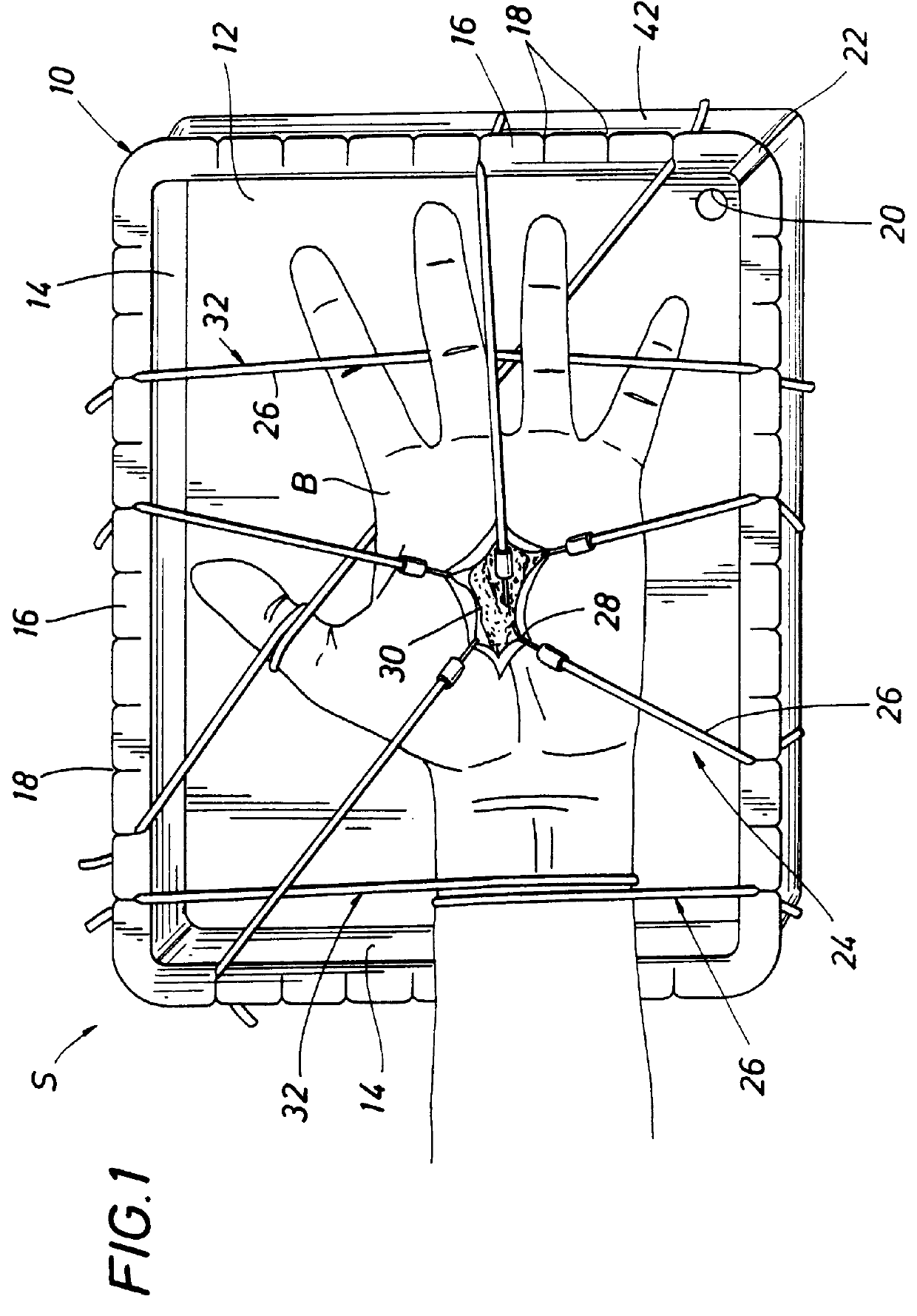
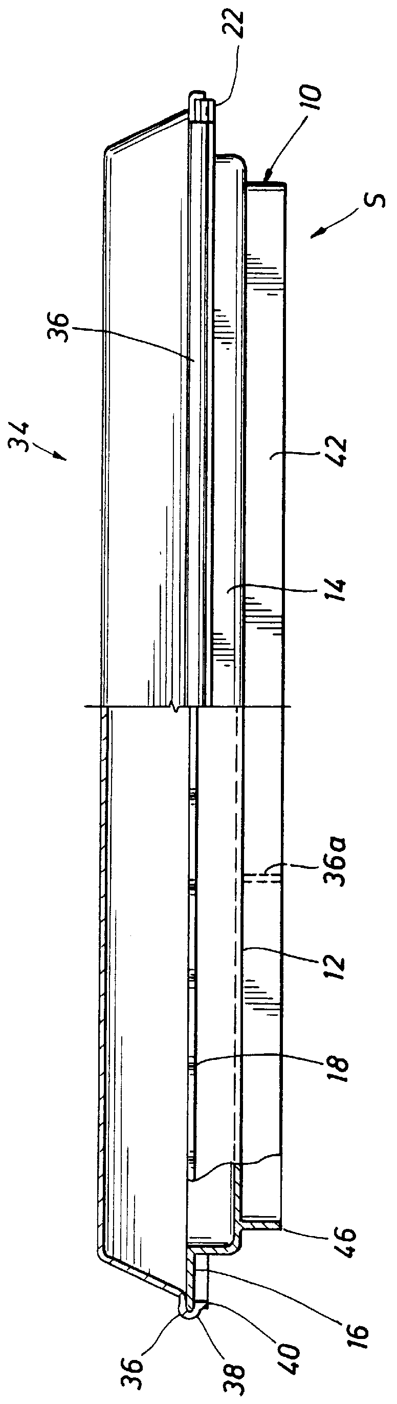
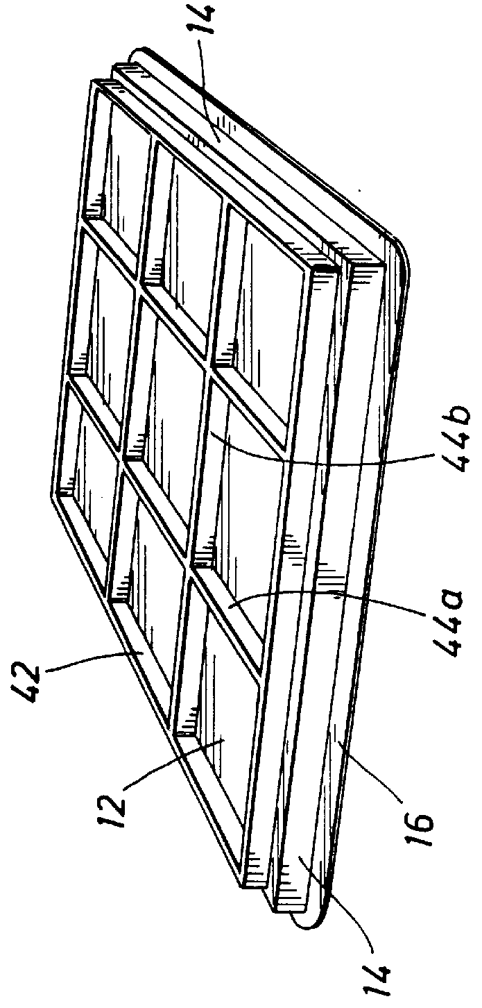
The surgical restraint system of the present invention, generally referred to as S, is shown in FIGS. 1-5. The surgical restraint system S includes a tray 10 adapted to receive a portion of a body, referred to as B, for example a hand (FIGS. 1 and 4) or foot. The tray 10 has a bottom member 12 from which a wall 14 extends to form a well to receive the body portion B and fluids associated with surgery or dissection. The bottom member 12 typically has a peripheral edge from which the peripheral wall 14 extends to form a square or rectangular well in tray 10. Alternatively, the bottom member 12 may be round having a wall 14 forming a round well in the tray 10. It is to be understood that the bottom member 12 can be various other shapes including, but not limited to, oval and elliptical. Also, the bottom member 12 may have a textured floor having a roughened surface including, but not limited to, a series of ridges or raised portions of the bottom surface for reducing movement of the an...
PUM
 Abstract
Description
Claims
Application Information