Separator for separating particles from a slurry

a separation device and slurry technology, applied in the direction of wet separation, gravity filter, gas current separation, etc., can solve the problems of increasing tailing losses, slow reduction of jigs, etc., and achieve the effect of improving the effectiveness of the separator and facilitating the process of separating dense parts

Inactive Publication Date: 2000-06-27
GRAY ALEXANDER HAMILTON
View PDF11 Cites 4 Cited by
  • Summary
  • Abstract
  • Description
  • Claims
  • Application Information

AI Technical Summary

Benefits of technology

A wire mesh screen with apertures between 1 to 4 mm in maximum dimension has been found particularly suitable for use in accordance with the present invention. Most preferably the apertures in the screen are about 2 mm in maximum dimension. In a particularly preferred arrangement the size of the apertures in the screen allows a majority of the metal values in the feed to pass through the screen into the lower component of the hutch and prevents larger particles of gangue with a relative density greater than the liquid in the hutch from passing through the screen. Preferably the screen will pass at 90% of the weight of dense particulates.
The bed may optionally include aggregate which is built up over time by the slurry or the aggregate may be specifically placed on the sheet or mesh to facilitate the process of separating the dense particulates. It has been found that choosing aggregates having a specific gravity less than that of the dense particulates being separated but higher than that of the particulates in the tailings may improve the effectiveness of the separator. Typically the aggregates will be present in the bed to a depth in excess of 50 mm more preferably 100 mm.

Problems solved by technology

The use of jigs today, however, is slowly diminishing due primarily to the fact that power and water consumptions are high in known jigs and the tailing losses are generally higher than in other separating processes.

Method used


Image

  • Separator for separating particles from a slurry
  • Separator for separating particles from a slurry

Examples


Embodiment Construction

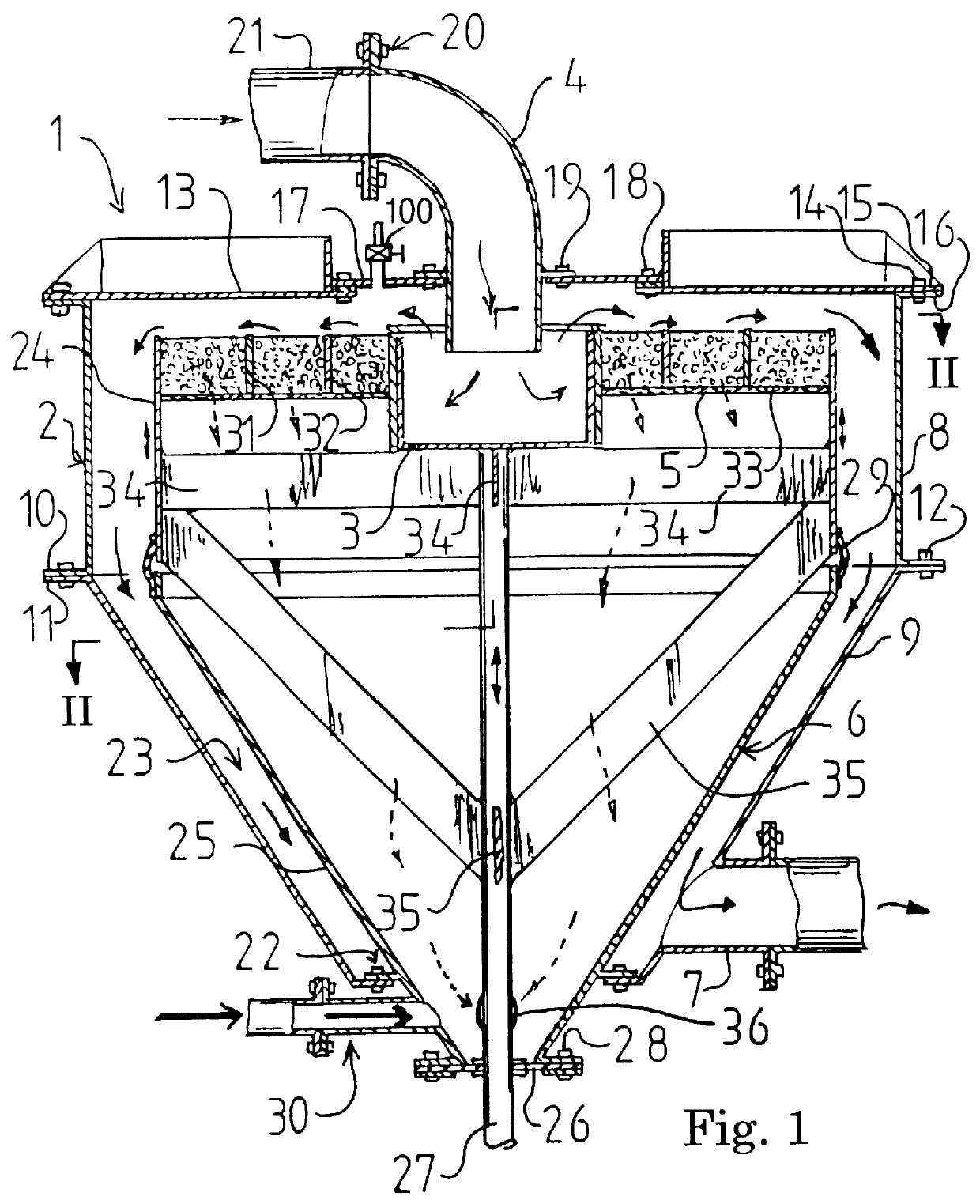
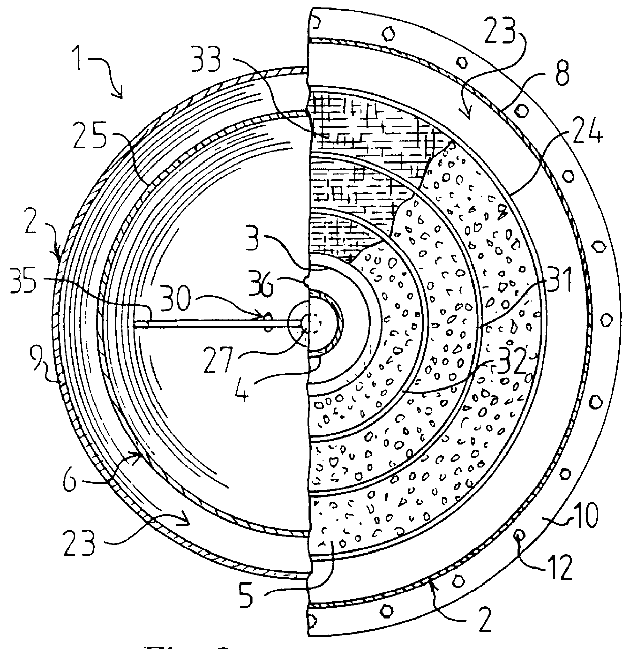
In use, a slurry is introduced into the sealed separator through slurry inlet 4 at a predetermined rate of flow. The slurry flows into sump 3. It is preferable if the sump 3 is substantially cylindrical so that a substantially horizontal flow of the slurry is produced in the sump. In the preferred arrangement illustrated the bed 5 is annular and surrounds the substantially cylindrical sump 3 so that the flow of slurry moves radially across the annular bed 5 in the direction of the outer edge of the annular bed as illustrated by the arrows. A liquid, preferably aqueous, is introduced into hutch 6 via regulating means 30 located adjacent the bottom of the hutch 6. Liquid is introduced into hutch 6 until the liquid completely submerges bed 5 and fills the separator. A valve 100 may be provided to completely purge air. The oscillating means, preferably a hydraulic ram drive, oscillates the bed 5 via movement of shaft 27.

As the slurry moves radially across bed 5 the rate of flow decrease...


PUM

PropertyMeasurementUnit
length of strokeaaaaaaaaaa
depthaaaaaaaaaa
diameteraaaaaaaaaa

Abstract

PCT No. PCT/AU95/00137 Sec. 371 Date Jul. 15, 1998 Sec. 102(e) Date Jul. 15, 1998 PCT Filed Mar. 15, 1995 PCT Pub. No. WO95/26232 PCT Pub. Date Oct. 5, 1995A separator (1) for separating dense particulates from slurry includes a sealed housing (2) enclosing a submerged screen bed (33) which allows dense particulates to fall into a hutch (6) from which they may be discharged. The housing has a slurry inlet (4) arranged to deliver slurry to a sump (3) which directs slurry to flow radially over the bed. An annular cavity (23) formed between the housing and bed receives tailings flowing off of the top of the bed. An outlet (7) from the annular cavity allows discharge of the tailings, and a liquid inlet (30) to the hutch provides an upward flow of liquid through the bed. The bed is agitated to assist passage of dense particulates.

Description

The present invention relates to a separator for separating particles from a liquid. More particularly, the invention relates to a jig for separating metal values from a liquid slurry.The present invention may be advantageously applied to jigs for separating metal values from gangue. It is convenient to hereinafter describe the invention in relation to that particular embodiment, however it is to be appreciated that the invention described herein may also be advantageously applied to other types of separating apparatus.Jigs are one of the most common separators used in the known process for separating heavy minerals or ores from lighter gangue. The "Harz Jig" is one of the older types of jigs and includes a submerged fixed screen through which water is pulsed as the ore and gangue moves across the screen, causing the lighter gangue to flow along the surface of the water over the screen and the heavier ores to gravitate down and through the screen. The "Hancock Jig" utilizes an oscil...

Claims


Application Information

Patent Timeline
Patent Type & Authority Patents(United States)
IPC IPC(8): B03B5/18B03B5/00B03B5/10
CPCB03B5/18B03B5/10
Inventor GRAY, ALEXANDER HAMILTON
Owner GRAY ALEXANDER HAMILTON
Why Eureka
Try Eureka