Image coding and decoding apparatus and methods thereof

a technology of image encoding and decoding apparatus, which is applied in the field of image encoding apparatus and image encoding apparatus, can solve the problems of inability to preserve prediction integrity, degradation of image quality, and lack of extensibility of ar

Inactive Publication Date: 2000-06-27
PANASONIC CORP
View PDF11 Cites 456 Cited by
  • Summary
  • Abstract
  • Description
  • Claims
  • Application Information

AI Technical Summary

Problems solved by technology

As a result, when a predicted image is constructed from these searched regions, overlapping or discontinuous portions occur in the image, resulting in a degradation in image quality.
However, with the above prior art method, since the predicted image is constructed using the motion vectors for the blocks horizontally and vertically adjacent to each target block, prediction integrity cannot be preserved unless the same reference image is used, and also the reference image is limited to only one frame (e.g. a previous one), the prior art thus has had the problem of lacking extensibili...

Method used


Image

  • Image coding and decoding apparatus and methods thereof
  • Image coding and decoding apparatus and methods thereof
  • Image coding and decoding apparatus and methods thereof

Examples


embodiment 1

(Embodiment 1)

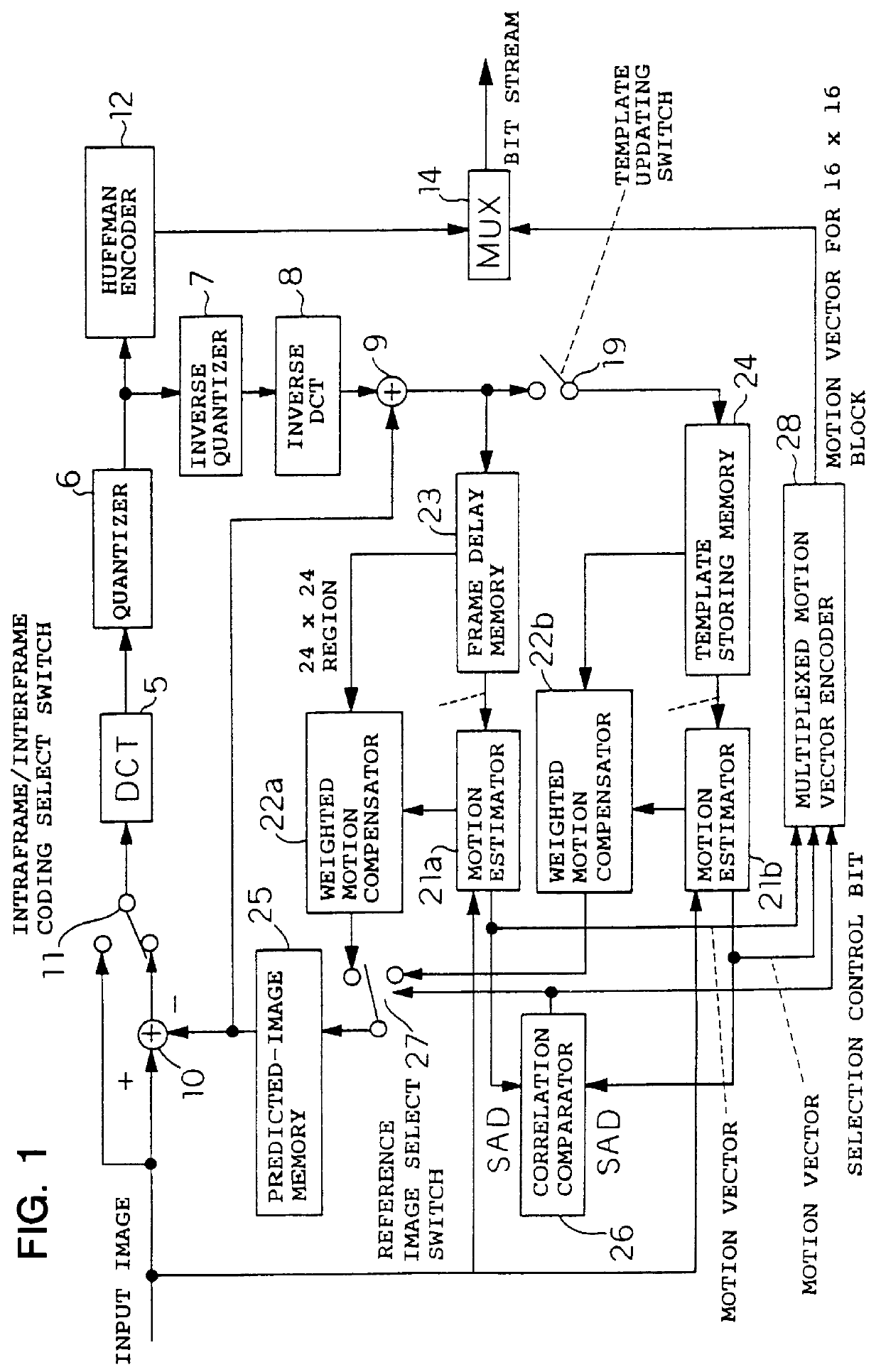
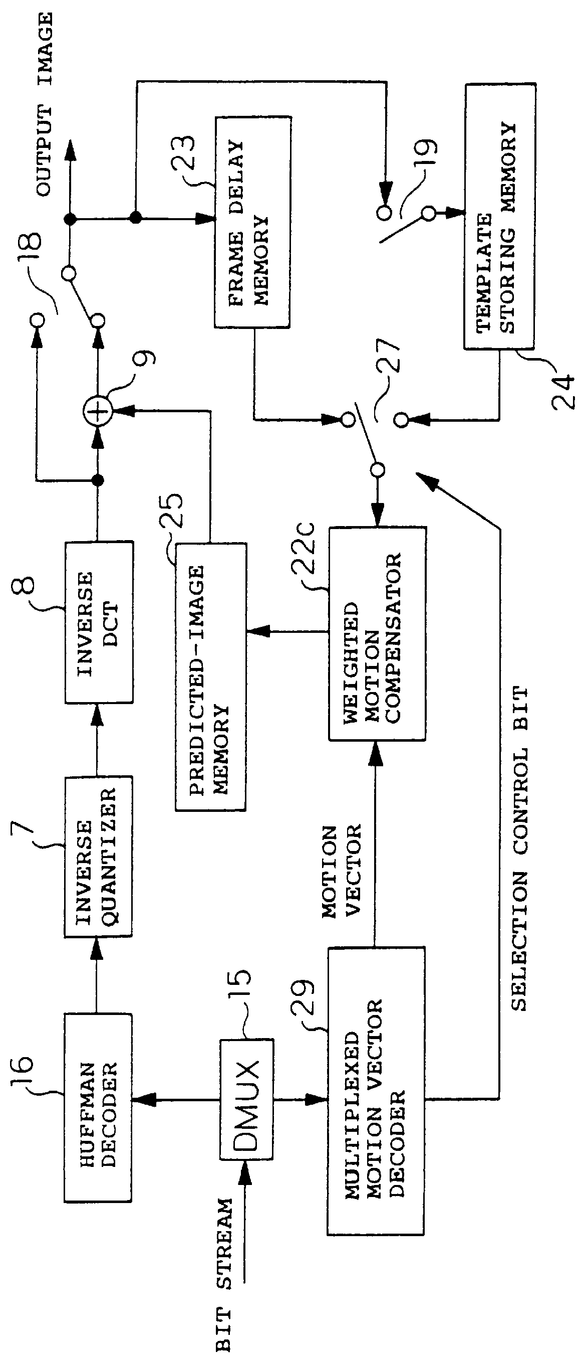
FIG. 1 is a block diagram showing the configuration of an image encoding apparatus according to a first embodiment of the present invention, and FIG. 2 is a block diagram showing the configuration of an image decoding apparatus corresponding to the image encoding apparatus. The image encoding apparatus comprises: a frame delay memory 23 for storing a reference image; a motion estimator 21a as a motion detecting means for detecting a motion vector based on the reference image and an input image; a weighted motion compensator 22a for creating a predicted image from the reference image by using the motion vector; a template storing memory 24 for storing a template (representative image) as a reference image; a motion estimator 21b as a motion detecting means for detecting a motion vector based on the input image and the template (which is a reference image different from the reference image stored in the frame delay memory 23); and a weighted motion compensator 22b for cr...

embodiment 2

(Embodiment 2)

FIGS. 6 and 7 are block diagrams showing the configuration of an image encoding apparatus according to a second embodiment of the present invention, and FIG. 8 is a block diagram showing the configuration of an image decoding apparatus corresponding to the image encoding apparatus. Major differences in this embodiment from the foregoing first embodiment are that the ordinary frame and template are processed separately and the data are packetized and output as different bit streams, and that an error-detecting code is appended to the ordinary frame and an error-correcting code to the template.

In addition to the configuration of the image encoding apparatus of FIG. 1, the image encoding apparatus of FIG. 6 further includes: an input selection switch 30 which switches the input image depending on whether the input image is an ordinary frame or a template; an output buffer 31 for an ordinary frame; an error-detection coding packetizer 32 for packetizing ordinary frame data...

embodiment 3

(Embodiment 3)

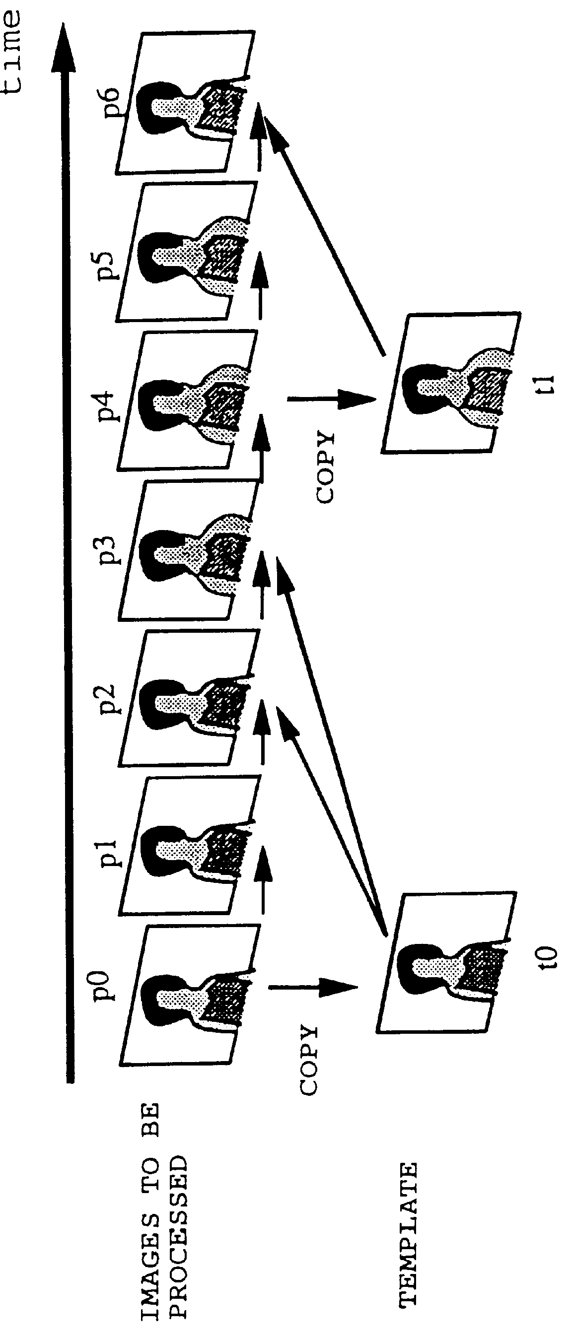
FIG. 12 is a schematic diagram showing relations between images to be processed and a template according to a third embodiment of the present invention. This embodiment is an extension of the foregoing second embodiment, and is intended for application where the template is a panoramic image or the like larger than an ordinary frame, for example, when ordinary frames p0 to p6 use a single template t0 as a reference, as shown in FIG. 12, or where reference blocks can be specified in advance in the reference image. FIG. 13 is a diagram showing processing timing for the images shown in FIG. 12; in the process shown, during the decoding of the template t0 the ordinary frames are sequentially decoded, starting with p0, for presentation for display.

To implement this, information indicating the upper left position and lower right position of a macroblock containing a template sub-region to be referenced (see FIG. 14) is appended, for example, at the head of each ordinary fram...


PUM


Abstract

To achieve an image encoding apparatus that has extensibility by not limiting an image to be referenced, and that can reduce processing time satisfactorily if the processing of an ordinary frame is skipped, the apparatus of the present invention comprises: motion detecting means for detecting a motion vector for each block of a prescribed size from a reference image and an input image; weighted motion-compensation means for, based on the detected motion vector, extracting from the reference image an area of a prescribed size which is wider than the prescribed block size and which contains an area corresponding to each block of the input image, and for creating a predicted image for the input image by applying a predetermined weight to each of pixels in the wider area and by using the weighted pixels of the wider area; a predicted-image memory for storing the predicted image; encoding means for taking a residual between the stored predicted image and the input image, and for encoding the residual; and decoding means for decoding the encoded image data and thereby obtaining a reference image.

Description

1. Field of the InventionThe present invention relates to an image encoding apparatus, an image decoding apparatus, etc. that are used to encode and decode moving image data, for example, in videophones and the like.2. Related Art of the InventionIn recent years, to transmit or record moving image data at low bit rates in videophone and videoconferencing systems, image compression techniques have been required to provide higher compression ratios for higher efficiency. These techniques have been standardized, for example, as MPEG 1 / 2 by ISO / IEC and H.261 and H.263 by ITU-T.FIG. 17 is a block diagram of a prior art image encoding apparatus, and FIG. 18 is an image decoding apparatus corresponding to the encoding apparatus, both implementing the ITU-T standard H.263.Referring to FIG. 17, when intraframe-coding an input image, an intraframe / interframe coding selection switch 11 is switched to the upper position. The input image, after discrete-cosine-transformed by a DCT 5, is quantize...

Claims


Application Information

Patent Timeline
IPC IPC(8): G06T9/00H04N7/26H04N7/50H04N19/50H03M7/36H04N19/102H04N19/103H04N19/105H04N19/126H04N19/132H04N19/139H04N19/152H04N19/159H04N19/162H04N19/172H04N19/176H04N19/186H04N19/189H04N19/196H04N19/42H04N19/423H04N19/46H04N19/463H04N19/503H04N19/51H04N19/517H04N19/57H04N19/577H04N19/61H04N19/625H04N19/65H04N19/70H04N19/85H04N19/86H04N19/89H04N19/895H04N19/91
CPCG06T9/001H04N19/23H04N19/61
Inventor ETOH, MINORU
Owner PANASONIC CORP
Why Eureka
Try Eureka