Aligning fixture for mold opening and closing mechanism

a technology of aligning fixture, which is applied in the direction of auxillary shaping apparatus, glass blowing apparatus, glass shaping apparatus, etc., can solve the problems of fixture not allowing alignment to be checked, difficult to reset the alignment in the future, and difficult to accurately perform, so as to achieve the effect of improving the mold opening and closing mechanism

Inactive Publication Date: 2000-07-11
EMHART GLASS SA
View PDF11 Cites 7 Cited by
  • Summary
  • Abstract
  • Description
  • Claims
  • Application Information

AI Technical Summary

Benefits of technology

It is accordingly an object of this invention to provide an improved mold open and close mechanism for an I.S. machine that will overcome these limitations.

Problems solved by technology

After alignment is completed, levers must be doweled making it difficult to reset alignment in the future.
Many steps in the aligning procedure make it difficult to perform accurately.
Also, the fixtures do not allow the alignment to be checked in the normal operating mode--only static alignment can be done.
It is also difficult to check the alignment when the machine is hot because of the time it takes to assemble the fixture to the section.

Method used


Image

  • Aligning fixture for mold opening and closing mechanism
  • Aligning fixture for mold opening and closing mechanism
  • Aligning fixture for mold opening and closing mechanism

Examples


Embodiment Construction

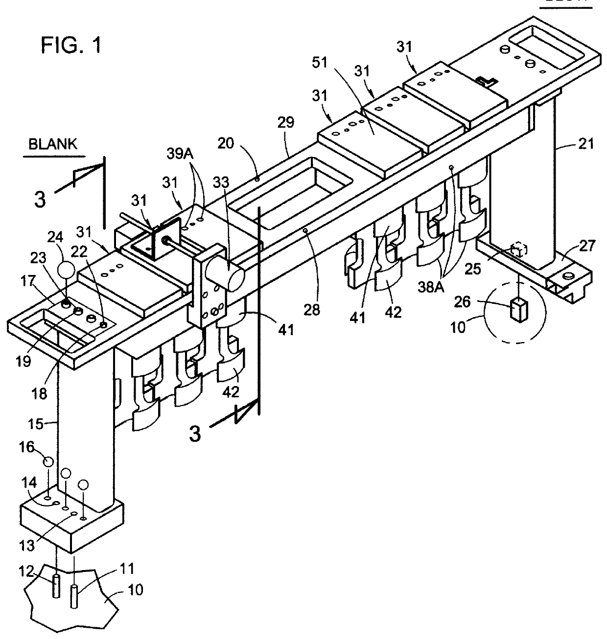
An I.S. machine has a plurality of individual sections (usually 8, 10 or 12) each having a section frame 10 (only small portions of the top wall of the frame are shown for purposes of clarity). Complete details of a state of the art I.S. machine with which this invention is intended to be used are disclosed in U.S. Pat. No. 5,824,131. Fixed to the top surface of each section frame is a round dowel 11 and a diamond dowel 12 which locate glass forming mechanisms including the mold opening and closing mechanism which are supported on the top surface of the section frame. These dowels are accurately located from the frame centerline. This centerline is a line lying in a plane perpendicular to the frame top surface that is located from one side edge so as to be equidistant from both the left hand and right hand side edges, and is the theoretical centerline.

A first upright 15 has holes 13, 14 which cooperate with the dowels 11, 12 when removably assembled to the section frame 10 and is cl...


PUM

PropertyMeasurementUnit
distanceaaaaaaaaaa
distancesaaaaaaaaaa
dimensionaaaaaaaaaa

Abstract

A mold opening and closing mechanism includes an aligning mechanism which has a horizontal mounting plate including a number of vertical openings for the number of molds, that is supported by a pair of spaced vertical uprights secured to the section frame top surface. A plurality of aligning cylinders are located in the vertical openings in the horizontal mounting plate and move parallel with the mold holder motion. Each cylinder includes surfaces configured to mate with the clamping surfaces of the mold holders. The axis of one of the aligning cylinders is held but not clamped at the theoretical centerline so it can move to the actual centerline when the mold holders are located at the advanced clamped closed position. A position transducer is mounted parallel with the mold holder motion to sense movement of the axis of one of the aligning cylinders and a computer receiving positional data from the transducer compares the theoretical centerline with the actual centerline determined from the data and defines a displacement offset for the displacement program to align the mold holders to the theoretical centerline.

Description

The present invention relates to I.S. (individual section) machines for manufacturing glass containers, and specifically, to the mold and blow mold opening and closing mechanisms for these machines.An I.S. machine has a plurality of identical sections each of which has a blank station which receives one or more gobs of molten glass and forms them into parisons having a threaded opening at the bottom (the finish) and a blow station which receives the parisons and forms them into bottles standing upright with the finish at the top. The blank station includes a pair of opposed blank molds which are displaceable from a separated position to a closed position. A vertically displaceable plunger of a plunger mechanism may be used to form the parison within the closed mold. The blow station includes a pair of opposed blow molds which are displaceable from a separated position to a closed position. An invert and neck ring holder mechanism which includes an opposed pair of neck ring arms whic...

Claims


Application Information

Patent Timeline
Patent Type & Authority Patents(United States)
IPC IPC(8): C03B9/353C03B9/40C03B9/16C03B9/00C03B9/197C03B9/34C03B9/30C03B9/44
CPCC03B9/165C03B9/353C03B9/3537C03B9/40C03B9/41
Inventor VOISINE, GARY R.FASCIANO, JOSEPH C.HWANG, DAVID K.
Owner EMHART GLASS SA
Why Eureka
Try Eureka