Softwall mining method and device

Inactive Publication Date: 2000-07-11
ROTHSCHILD KEITH R
View PDF8 Cites 8 Cited by
  • Summary
  • Abstract
  • Description
  • Claims
  • Application Information

AI Technical Summary

Problems solved by technology

Simpson does not accommodate soft, plastic, fluid, loose, unstable, clayey, sandy, dirt, soil, or similar (earthy) ground conditions

Method used


Image

  • Softwall mining method and device
  • Softwall mining method and device
  • Softwall mining method and device

Examples


Embodiment Construction

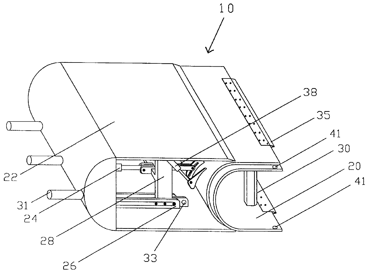
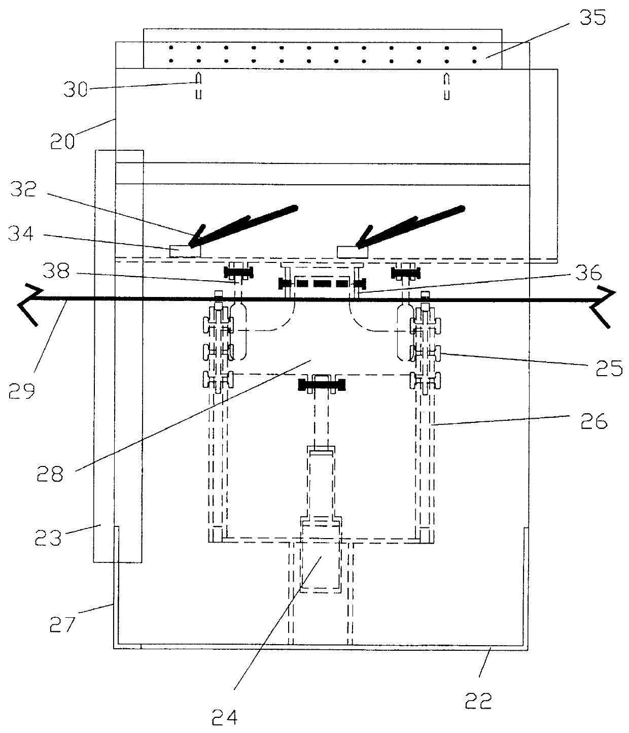
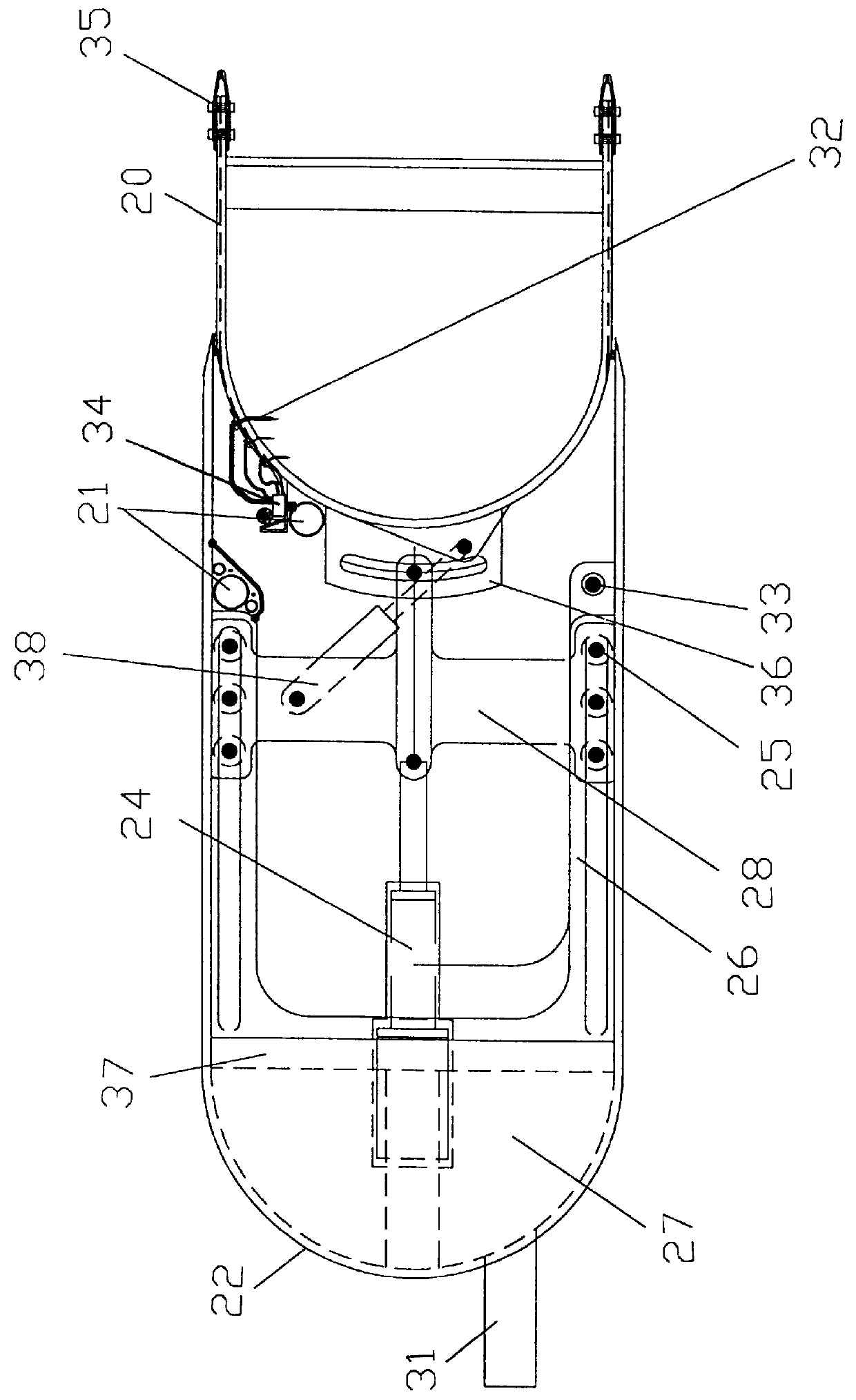
A typical embodiment of the softwall mining equipment of the invention is illustrated in FIGS. 1 through 4. FIG. 1 is an isometric schematic view of a softwall mining device 10 according to the invention. The device 10 consists of a face sluicing chamber 20 partially enclosed within a rear and rear bearing support or shell 22. The function of the device 10 is to remove ore matrix away from the ore face. This is accomplished by the forward extension of the face sluicing chamber 20 from within the rear bearing support 22 through the actuation of an extension ram 24. Forward movement is enhanced by the action of a plurality of cutting edge injection nozzles 35 mounted on the face sluicing chamber 20, as also seen in detail in FIG. 4A. Elongated slots 41 are provided to movably join the tongue and grooved edges of the face sluicing chamber 20 together with other softwall mining devices.

Rigidly mounted on the rear bearing support 22, extension guides 26 provide directional thrust control...


PUM


Abstract

Slurryable ore where the overburden is unstable and subject to collapse is mined from substantially parallel elongated main trenches connected by a perpendicular trench at the bottom of the mineral seam. A plurality of softwall mining devices supported by face equipment is placed in the perpendicular trench. The devices slurry the mineral material and move into the mineral seam as the overburden sloughs behind the mining devices. The subsided overburden is supplemented as necessary with injected material. Slurried mineral flows to the parallel trenches for removal to the surface. After the softwall devices have advanced the length of the parallel trenches, the devices are withdrawn and placed in additionally developed trenches elsewhere in the ore reserve.

Description

1. Field of the InventionThis invention pertains in general to the field of mining and, in particular, to a novel device and method for mining slurryable, shallow mineral deposits with earthy overburden in a longwall fashion.2. Description of the Prior ArtSurface mining is and has historically been employed to recover stratified minerals under overburden to economic depths. Underground mining is traditionally employed when overburden depths exceed those economically removable by surface mining or when major surface disturbance is unacceptable.Prior inventions have been patented for longwall mining of reserves using trenched entry where overburden is sufficiently competent to bridge over longwall shearing and conveying equipment and where floor strata are competent to withstand mining stresses. (See Simpson, U.S. Pat. No. 4,017,122.) Simpson does not accommodate soft, plastic, fluid, loose, unstable, clayey, sandy, dirt, soil, or similar (earthy) ground conditions often encountered i...

Claims


Application Information

Patent Timeline
IPC IPC(8): E21C25/60E21C41/16E21C41/00E21C25/00
CPCE21C25/60E21C41/16
Inventor PETERSON, RANDALL D.
Owner ROTHSCHILD KEITH R
Why Eureka
Try Eureka