However, when the non-contact developing method is compared with a contact developing method, the latter method can carry the toner to an electrostatic latent image portion mechanically, while the non-contact developing method is required to fly the toner by electrostatic force and is unable to assure sufficient development unless the electrical property of the toner and the developing conditions of the developing unit are fully optimized.
Accordingly, the above-mentioned publication No. 41(1966)-9475 teaches merely the basic idea of the non-contact developing method and discloses nothing about the property of the toner and the developing conditions, so that it is difficult to implement it.
This is because a large toner charge-to-
mass ratio was believed to increase image-force Fi and to decrease the flying property of the toner, thus considerably decreasing the developability, because the image-force Fi, which is an electrostatic
adhesive force of the toner, increases in proportion to the square of the charge-to-
mass ratio.
Due to that, there has been a problem that the toner having a
small particle size which should otherwise be very effective in improving an
image quality cannot be used in the non-contact developing method.
The toner in the non-contact developing method has been limited to those having a
large particle size and having a small charge-to-
mass ratio.
Further, when the non-magnetic monocomponent toner is used, the toner cannot be fully conveyed unless the fluidity of the toner is good, because the toner cannot be conveyed by magnetic force.
However, the flying-development using the toner having the
large particle size and the low charge-to-
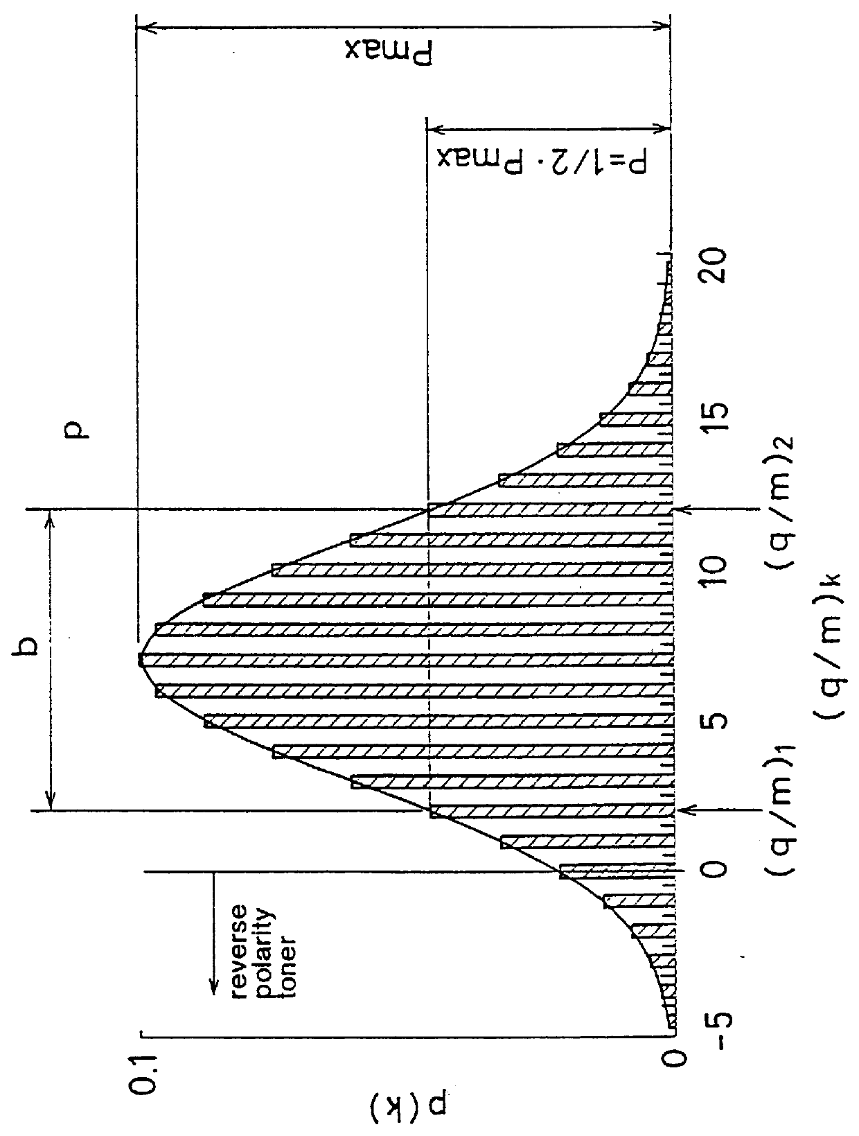
mass ratio to improve the flying property thereof as described above has had a problem that it is apt to produce wrong sign toners (reverse polarity toners) and to cause background
fog and a reduction of sharpness of edge, thus deteriorating the
image quality.
This problem is outstanding especially when monocomponent toner is used.
Further, the method of developing the non-magnetic monocomponent toner in a DC
electric field has had a problem that the toner layer is apt to be flown apart, as common to the non-magnetic toner.
That is, while the non-magnetic toner is carried on the toner carrier mainly by image-force (electrostatic
adhesive force) because it cannot be laminated and carried on the toner carrier by magnetic force like magnetic toner, the toner is apt to be flown apart because the toner having a small charge-to-
mass ratio decreases the image-force, thus deteriorating the developability.
Although the method of developing the non-magnetic monocomponent toner in the DC
electric field is suitable for color development, it has a number of disadvantages in terms of
image quality as described above as compared to the conventional methods such as a two-component magnetic
brush development.
While a method of developing a black toner by the two-component magnetic
brush development by using a toner having a
small particle size and of developing only color toners by the non-contact developing method by using non-magnetic monocomponent toners having a relatively
large particle size has been adopted sometimes as practical means for putting into use, it has had a problem that it complicates the equipment.
The toner having a large particle size has had a problem that a distance between a position of the center of gravity of the toner at the outermost surface of the toner carrier and an electrostatic latent image is separated, even though the development gap is constant, so that an electric
field pattern of the latent image acting on the toner attenuates, thus decreasing a resolution of the image after the development.
Beside them, the non-contact development has had a problem of a phenomenon that a density at edge is emphasized depending on a development pattern due to the relation of the
peripheral speed of the toner carrier with that of the electrostatic latent image holder.
Although the method disclosed in Japanese Patent Laid-open Publications No. Hei. 5(1993)-232802 and No. Hei. 5(1993)-297711 allow the toner having a
small particle size to be used, they have problems such that the toner carrier is confined on a belt, separate means for applying
mechanical vibration or
impact is necessary and the equipment is complicated, thus increasing the cost.

