Sacrificial erosion control features for chemical-mechanical polishing process

Inactive Publication Date: 2000-07-11
INTEL CORP
View PDF10 Cites 76 Cited by
  • Summary
  • Abstract
  • Description
  • Claims
  • Application Information

AI Technical Summary

Problems solved by technology

These layers and contours can cause high stress, cracking and electromigration in metal layers, and optical aberrations, among other problems.
A problem resulting from CMP is erosion of the underlayer,

Method used


Image

  • Sacrificial erosion control features for chemical-mechanical polishing process
  • Sacrificial erosion control features for chemical-mechanical polishing process
  • Sacrificial erosion control features for chemical-mechanical polishing process

Examples


Embodiment Construction

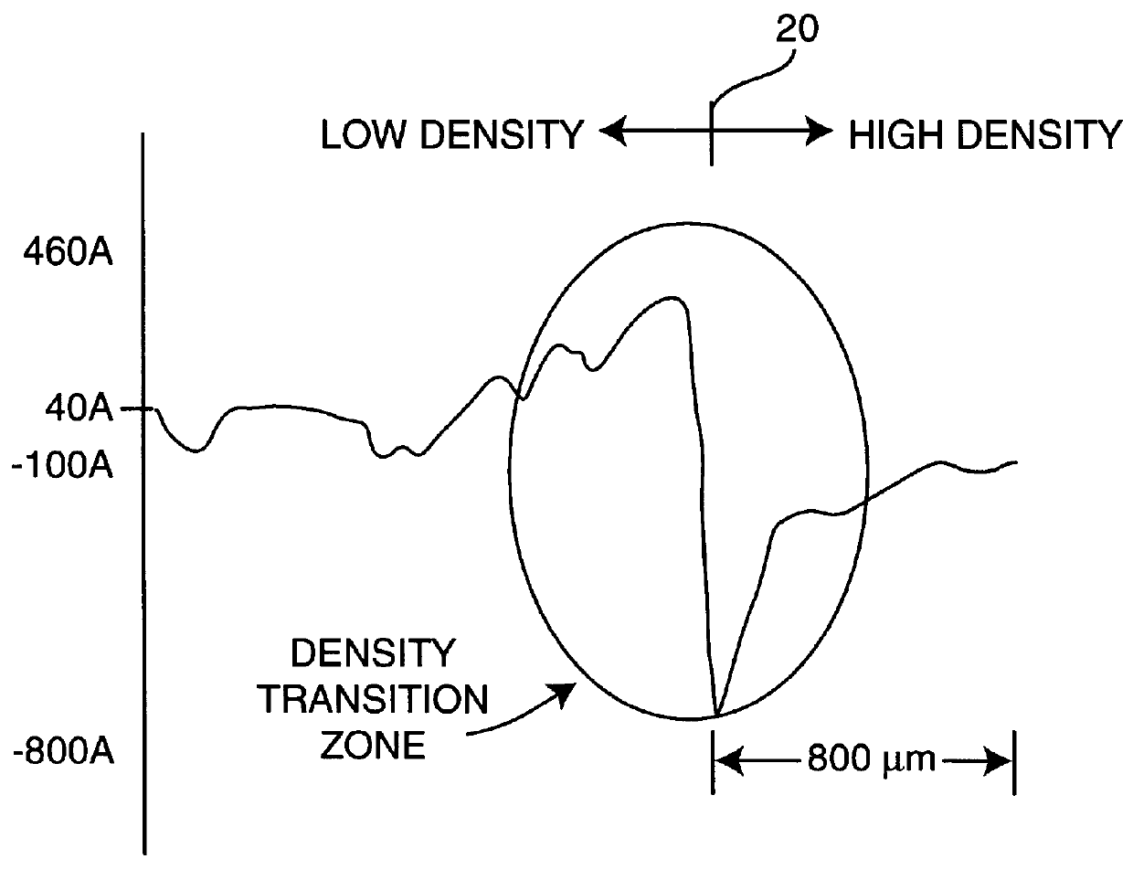
A method and apparatus for reducing the affects of erosion that occur during chemical-mechanical polishing (CMP) sometimes referred to as "dishing" is described. In the following description numerous specific details such as specific features, feature heights, feature densities, etc., are set forth to provide a thorough understanding of the present invention. It will be apparent that these specific details are not required to practice the present invention. In other instances, well-known steps, such as the deposition of well-known layers and lithography steps, well-known in the art, are not described in detail in order not to obscure the present invention.

Present Invention In Connection With Alignment Marks

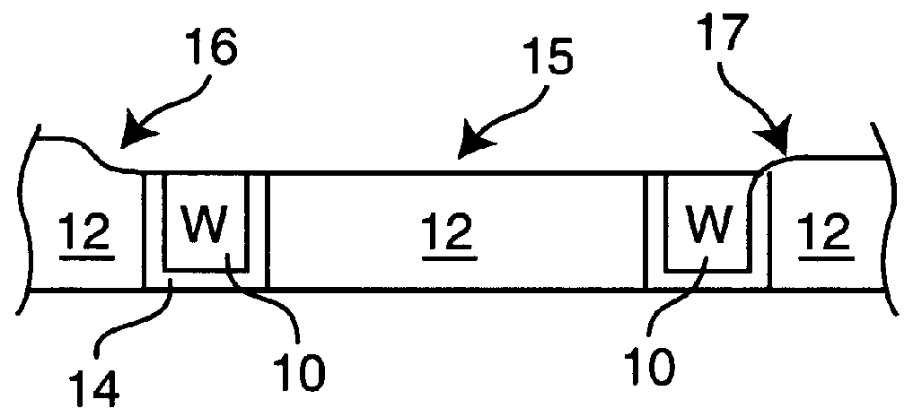
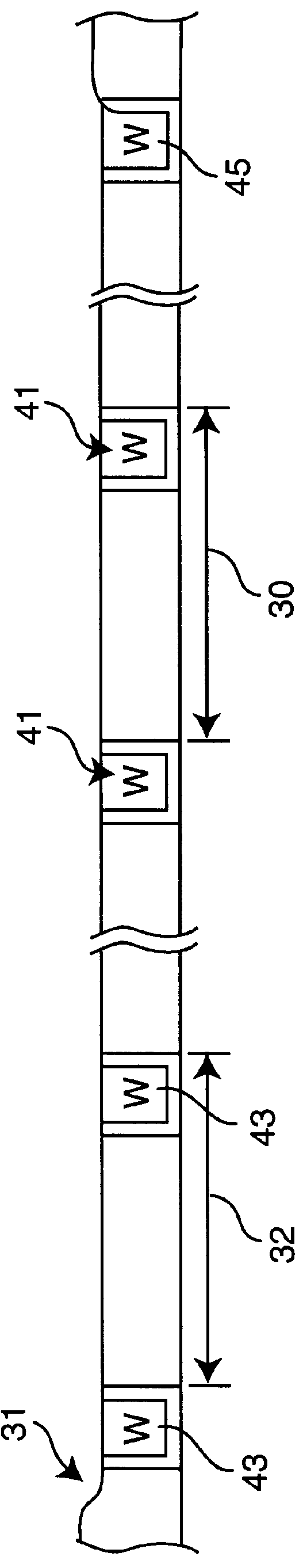
One application for the present invention is in connection with alignment marks such as the alignment marks shown in FIG. 1. In the following description tungsten filled trenches forming alignment marks are described. The present invention, however, may be used with other marks, f...


PUM


Abstract

A method and apparatus for compensating for the effects of nonuniform planarization in chemical-mechanical polishing (CMP) such as the erosion occurring from the removal of titanium nitride/tungsten films is disclosed. In the context of alignment marks, dummy marks are disposed on both sides of the actual alignment marks providing a similar feature density as the alignment marks. During the CMP, the dummy marks reside in the area of nonuniform erosion, leaving the actual marks in an area of uniform erosion. The present invention may also be used to control underlayer erosion variations in the high feature density device areas adjacent to the low feature density open areas by providing dummy features in the low feature density areas.

Description

1. Field of the Invention.The invention relates to the field of the chemical-mechanical polishing of semiconductor wafers.2. Prior Art and Related Art.In semiconductor processing rough or undulation layers, or abrupt changes in contours are avoided. These layers and contours can cause high stress, cracking and electromigration in metal layers, and optical aberrations, among other problems.One early technique for eliminating the abrupt contours in a glass layer resulting from etching contact openings was to reflow the glass layer as taught by U.S. Pat. No. 3,825,442. Numerous planarization methods are also used on entire layers such as chemically etching-back an interlayer dielectric (ILD) as taught in U.S. Pat. No. 4,775,550. More recently, chemical-mechanical polishing (CMP) has been used for planarization, such as shown in U.S. Pat. Nos. 5,554,064 and 5,635,083. Another technique used to promote planarized surfaces is the fabrication of dummy features to, for example, provide more...

Claims


Application Information

Patent Timeline
IPC IPC(8): H01L21/02H01L23/544H01L21/321H01L21/768H01L21/70
CPCH01L21/3212H01L23/544H01L21/7684H01L2223/5442H01L2223/54426H01L2223/54453H01L2223/5446H01L2924/0002H01L2924/00
Inventor MAXIM, MICHAEL A.KOCSIS, MICHAELHSIEH, NINGPRINCE, MATTHEWCADIEN, KENNETH C.
Owner INTEL CORP
Why Eureka
Try Eureka