
Electronic apparatus having a high-speed communication bus system such as an I.sup.2 C bus system

Inactive Publication Date: 2000-07-18
FUTURE LINK SYST
View PDF6 Cites 47 Cited by
  • Summary
  • Abstract
  • Description
  • Claims
  • Application Information

AI Technical Summary

Benefits of technology

It is an object of the invention to increase the speed with which message transfer can occur in a communication bus transfer system.
As a result, a novel master station that is capable of driving the potential of the bus conductor against a higher current than the maximum current can communicate at higher speed after arbitration if this master station sets up only communication in which the potential of the bus conductor does not need to be driven against the load circuit by any station that is incapable of driving the potential of the bus signal conductor against the load circuit when more than the maximum current is supplied.
In an embodiment of the electronic apparatus according to the invention, the bus conductor is a clock signal conductor and the bus also contains a data signal conductor, data being transmitted via the data signal conductor, synchronized by a signal on the clock signal conductor. In this embodiment, the stations are also connected to the data signal conductor on a wired logic basis, but the load circuit connected to the data signal conductor supplies the same current to the data signal conductor at corresponding instants during and after arbitration, that is, at instants in which the load circuit connected to the clock signal conductor supplies different currents. Validation of data always occurs on the same direction of edges of the clock signal and therefore the frequency of edges on the data signal conductor only needs to be half the frequency of edges on the clock signal conductor. As a result, a gain in speed can be attained even though additional current is supplied only to the clock signal conductor.

Problems solved by technology

In the I2C protocol a master station controls the potential of the clock signal conductor, but other stations which participate in communication can delay clockpulses.
Although this maximum imposed on the current is unavoidable if one wants to communicate with stations satisfying the I2C standard, the maximum current specified for the I2C bus is a drawback because it limits the speed of potential level changes on the bus conductors and thereby the maximum speed of message transfer.

Method used


Image

  • Electronic apparatus having a high-speed communication bus system such as an I.sup.2 C bus system
  • Electronic apparatus having a high-speed communication bus system such as an I.sup.2 C bus system
  • Electronic apparatus having a high-speed communication bus system such as an I.sup.2 C bus system

Examples


Embodiment Construction

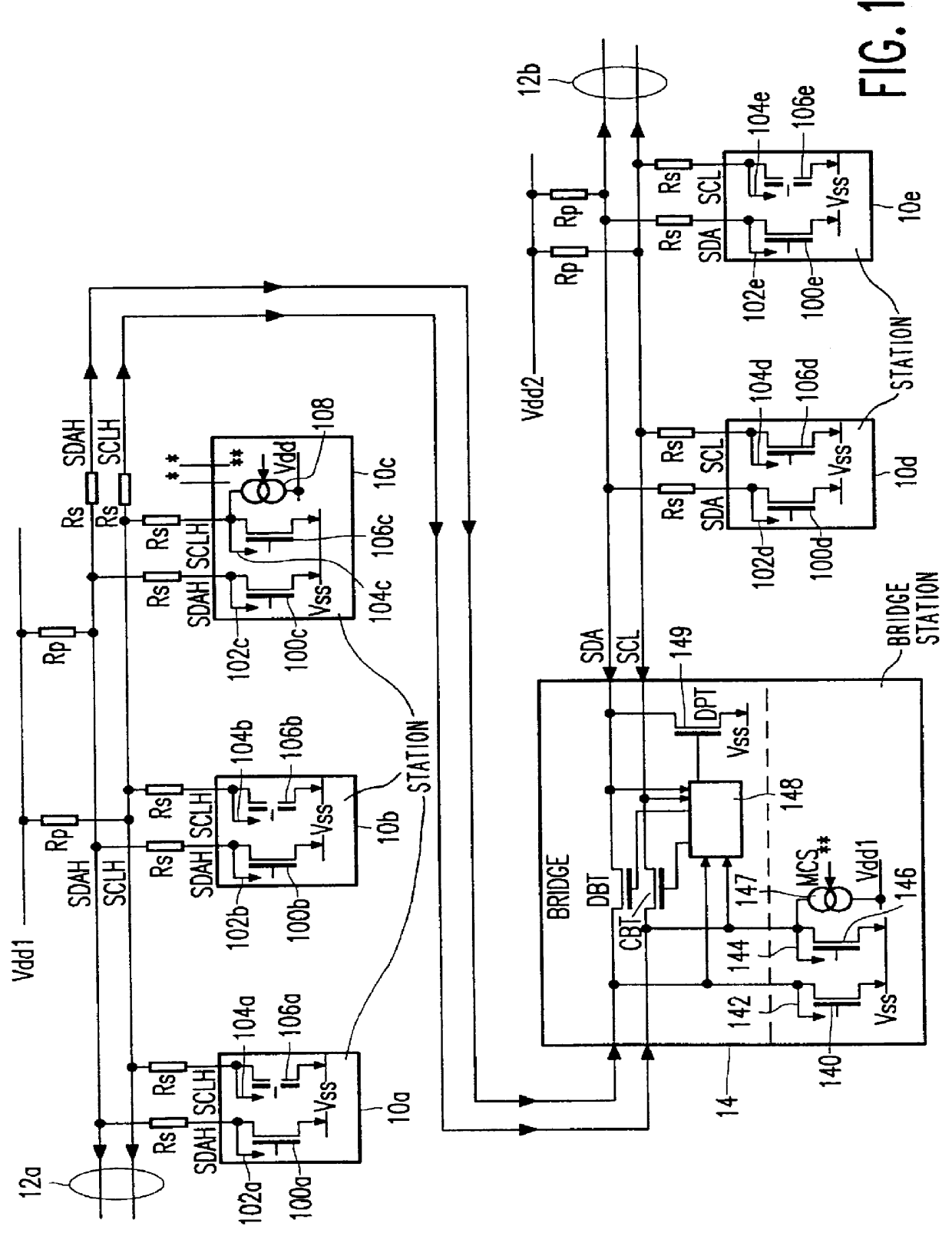
FIG. 1 shows an apparatus according to the invention with a communication bus 12a,b containing a first and second section 12a, 12b. The apparatus contains a number of stations 10a-e connected to the communication bus 12a,b and a bridge station 14 connecting the two sections 12a,b of the communication bus. Each section of the bus 12a,b contains a clocksignal conductor SCL, SCLH and a datasignal conductor SDA, SDAH. The stations 10a-e are connected to the conductors 12a,b via resistors Rs, which serve for suppressing interfering pulses and ringing due to excessively fast signal edges.

The stations 10a-e are divided into a first and second subset 10a-c, 10d-e, corresponding to the first and second section 12a,b of the bus respectively. Each station 10a-e belonging to a subset 10a-c, 10d-e has connections to the clocksignal conductor SCL, SCLH and the datasignal conductor SDA, SDAH of the section 12a,b corresponding to that subset 10a-c, 10d-e.

In each station 10a-e the connection to the ...


PUM


Abstract

An electronic apparatus contains a bus conductor, a load circuit connected to the bus conductor for pulling a potential of the bus conductor towards a quiescent level and stations interconnected by the bus conductor. At least one of the stations contains a wired logic drive circuit and an arbitration circuit connected to the wired logic drive circuit for executing an arbitration wherein the wired logic drive circuits of different ones of the stations may each pull the potential against the load circuit. The electronic apparatus comprises a detector for producing a detection signal when the at least one station wins the arbitration. In response to the detection signal the load circuit is switched to an increased current supply capability state. In the increased current supply capability state the load circuit supplies a greater current to the bus conductor than during arbitration at least at times when the potential starts changing towards the quiescent level.

Description

BACKGROUND OF THE INVENTIONThe invention relates to an electronic apparatus comprising stations capable of communicating via a bus conductor. The invention also relates to a station for use in such an electronic apparatus.Such an electronic apparatus is known from the commercially available I2C bus system described in the "Data Handbook IC20: 80C51-based 8-bit microcontrollers" issued by Philips Semiconductors in 1994, pages 1141-1159.The I2C bus uses two bus conductors: a clocksignal conductor (SCL) carrying a clocksignal and a datasignal conductor (SDA) carrying a datasignal. Message transfer via the I2C bus requires the stations to participate in various operations according to a signal protocol.In the I2C protocol a master station controls the potential of the clock signal conductor, but other stations which participate in communication can delay clockpulses. This allows the other stations to take as much time as needed for handling the data. To delay the clock pulses the statio...

Claims


Application Information

Patent Timeline
IPC IPC(8): G06F13/00
CPCG06F13/00
Inventor SCHUTTE, HERMAN
Owner FUTURE LINK SYST
Features
  • Generate Ideas
  • Intellectual Property
  • Life Sciences
  • Materials
  • Tech Scout
  • Unparalleled Data Quality
  • Higher Quality Content
  • 60% Fewer Hallucinations
Learn More