Drill rod and method for its manufacturer

a technology of a drill rod and a manufacturer, which is applied in the direction of furnaces, heat treatment equipment, and accessories of boreholes/wells, can solve the problems of the type of rod most susceptible to corrosion fatigue, the weak "soft" zone of the immediate side of the drill rod, and the risk of corrosion fatigue, so as to achieve the effect of enduring high impact loads and unique resistance to corrosion fatigu

Inactive Publication Date: 2000-08-01
SANDVIK AB
View PDF2 Cites 28 Cited by
  • Summary
  • Abstract
  • Description
  • Claims
  • Application Information

AI Technical Summary

Benefits of technology

One object of the present invention is to provide a friction welded drill rod which has a unique res

Problems solved by technology

However, due to the friction-generated heat, drill equipment manufactured from conventional drill steel develops weak "soft" zones on both immediate sides (i.e., heat-affected regions) of the weld.
Water flushing results in a risk for corrosion fatigue, however,

Method used


Image

  • Drill rod and method for its manufacturer
  • Drill rod and method for its manufacturer
  • Drill rod and method for its manufacturer

Examples


Embodiment Construction

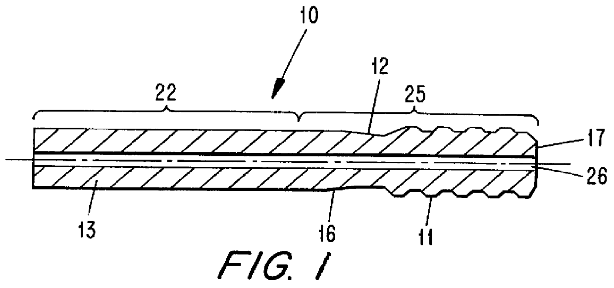
The drill rod 10 for percussive drilling comprises first end and second components 25, 22. The first component 25 comprises an externally threaded portion 11 merging with a clearance portion 12, which merges with a short rod portion 16 having a larger diameter than the clearance portion. The threaded portion 11 connects to a striking surface 17. The first component 25 is joined by a friction weld 27 (see FIG. 4A) to the second component 22, which preferably is a long rod portion pr bit 13. A flush channel 26 is provided centrally in the drill rod 10. The free end of the short rod portion 16 prior to welding is substantially of the same diameter as that of the rod portion 13. Instead of being external, the thread portion could constitute an internal thread portion.

To friction weld the components 22, 25 together, the component 25 is held non-rotatable, and the component 22 is rotated, although the reverse would be possible. The components 22, 25 are made of steel and before friction w...


PUM

PropertyMeasurementUnit
Fractionaaaaaaaaaa
Fractionaaaaaaaaaa
Fractionaaaaaaaaaa

Abstract

A rock drilling rod is manufactured by placing free ends of first and second hollow rod components in abutment, and establishing relative rotation between the free ends to friction weld those free ends together. The first component comprises a thread and a clearance portion disposed adjacent the thread. The first component has a hot hardness value of at least about 170 HV1 at 600 DEG C. Prior to friction welding the components together, the thread, clearance portion and central passage of the first component are heat treated against corrosion fatigue. Then, the thread is high frequency hardened to a depth at least as great as the heat treated layer. Following the welding, the weld is cooled while keeping a core hardness of the respective portions of the first and second components disposed immediately adjacent the weld no lower than 390 HV1.

Description

TECHNICAL BACKGROUNDConventional rods for rock drilling either have a thread machined directly in the rod, or a thread machined in a rod end forged to a diameter bigger than the rod diameter. Instead of forging up the dimension of rods it is possible to attach, by friction welding, end pieces or guiding pieces having diameters bigger than the rod diameter. Conventional rock drilling rods are most often manufactured from hollow rods, and shank adapters are most often manufactured from solid rods. For threaded rods, at least one thread is often machined in a bumped up (forged) end having a diameter bigger than the rod diameter, while the shank adapters often are machined from rounds.Instead of forging up the dimension or using extensive machining it has been more and more common to employ a friction weld to interconnect pieces having big differences in diameter. However, due to the friction-generated heat, drill equipment manufactured from conventional drill steel develops weak "soft"...

Claims


Application Information

Patent Timeline
IPC IPC(8): B23K20/12C22C38/44E21B17/00E21B17/02B23K20/24B25D17/02C21D9/00C22C38/00C22C38/58
CPCB23K20/129C22C38/44E21B17/00B23K2201/06E21B17/0426B23K2101/06
Inventor LUNDELL, LARS-GUNNAR
Owner SANDVIK AB
Why Eureka
Try Eureka