Electrical rotating actuator for forming a weaving loom shed

a technology of rotating actuator and weaving loom, which is applied in the direction of weaving, magnetic circuit rotating parts, and shape/form/construction of magnetic circuits, etc., can solve the problems of motors having a low inertia and loom overdimension

Inactive Publication Date: 2000-08-22
STAUBLI FAVERGES SA
View PDF15 Cites 17 Cited by
  • Summary
  • Abstract
  • Description
  • Claims
  • Application Information

AI Technical Summary

Problems solved by technology

This known type of device necessitates considerable power for maneuvering the griffe frames, which power is furnished by the drive shaft of the weaving loom, this leading to the loom being o...

Method used


Image

  • Electrical rotating actuator for forming a weaving loom shed
  • Electrical rotating actuator for forming a weaving loom shed
  • Electrical rotating actuator for forming a weaving loom shed

Examples


Embodiment Construction

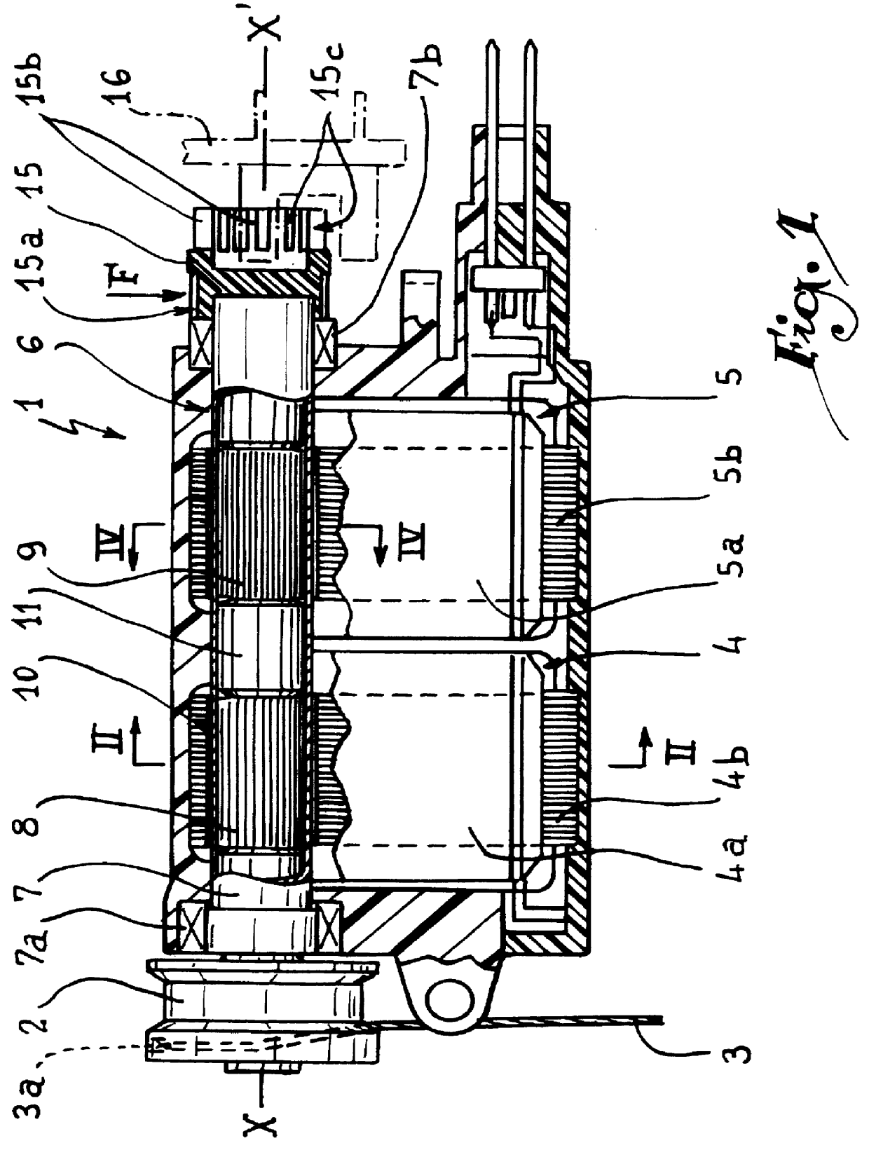
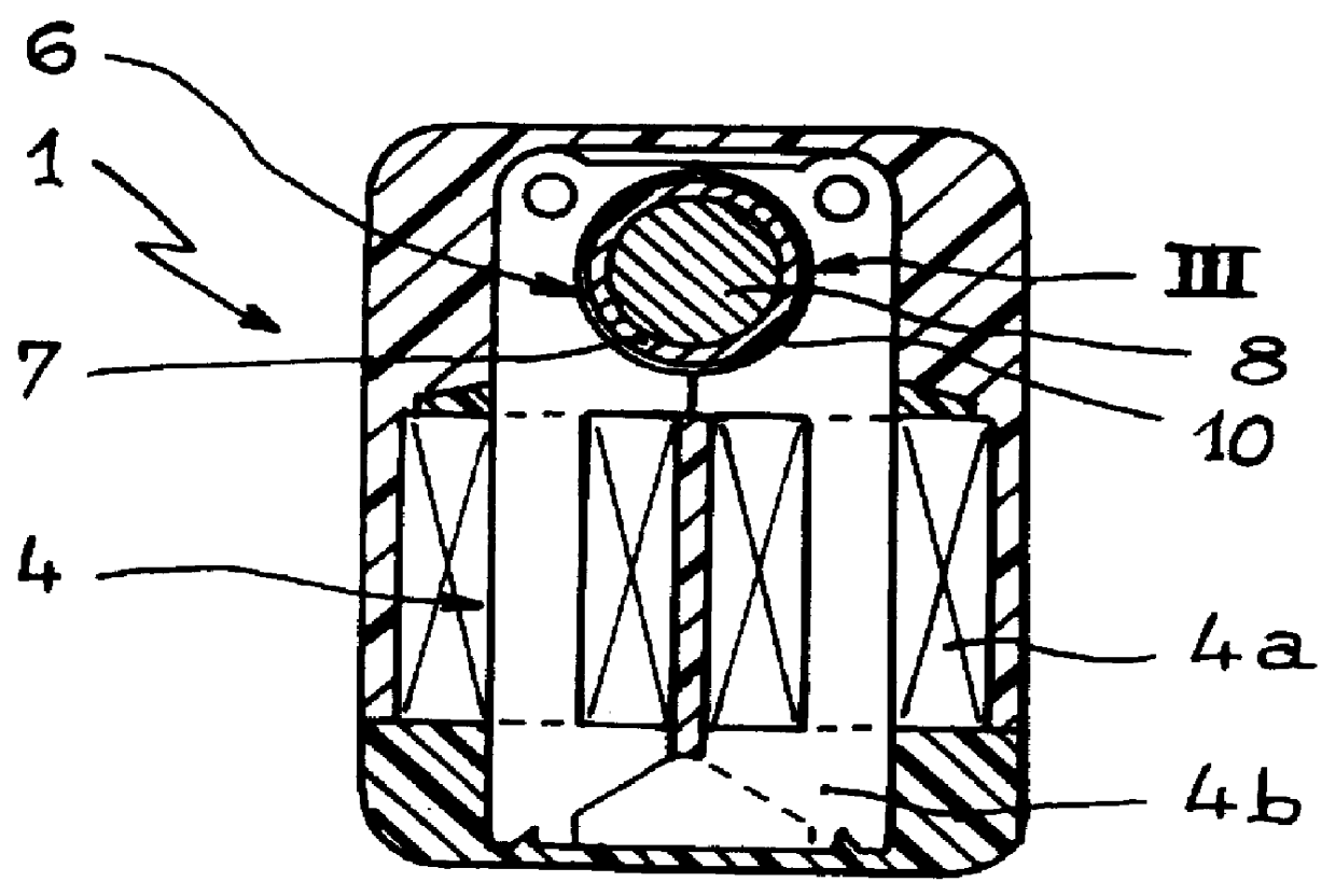
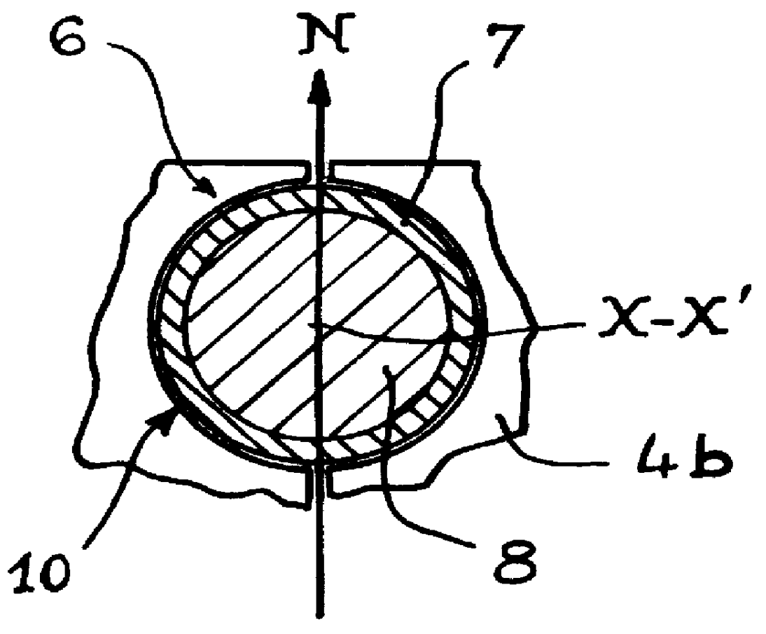
Referring now to the drawings, and firstly to FIG. 1, the electrical rotating actuator 1 is intended to ensure winding, on a pulley 2, of a harness cord 3 connected to one or more warp yams of a weaving system of Jacquard type. The actuator 1 is a two-phase actuator. It comprises a stator formed by two stator elements 4 and 5 offset in a direction defined by axis XX'. These elements 4 and 5 are overall aligned and adapted to cooperate with a rotor 6 formed by a tube 7 centered on the axis XX'. The tube 7 is preferably made of a magnetic material, such as for example brass. The tube 7 is supported in the body of the actuator I by two bearings 7a and 7b formed by ball bearings. The use of ball bearings allows an excellent yield in rotation. The tube 7 contains two permanent magnets 8 and 9, of substantially cylindrical shape, offset along axis XX' and disposed opposite the two stator elements 4 and 5. These elements 4 and 5 comprise windings 4a and 5a of electrically conducting wire, ...


PUM


Abstract

An electrical rotating apparatus for controlling a harness cord associated with the shed of a weaving loom which includes an actuator including a rotor and a stator. The rotor is formed of at least two permanent magnets which are mounted within a tube so as to be spaced axially with respect to one another and wherein a plurality of stator elements are also provided offset axially relative to an axis of rotation of the rotor such that each of the plurality of rotors corresponds with a separate one of the plurality of stators. The polarities of one or the other of the permanent magnets or the stator elements are offset angularly relative to the axis of rotation.

Description

The present invention relates to an electrical actuator for forming the shed in a weaving loom, particularly for controlling the harness cords of a weaving system of the Jacquard type or the frames of a dobby. The invention also relates to a weaving system comprising such an actuator, and to a weaving loom equipped with such a system.DISCUSSION OF THE RELATED ARTIn weaving systems of the Jacquard type, it is known to drive, in phase opposition, two frames each bearing a plurality of griffes or horizontal knives adapted to displace, vertically, hooks connected to the harness cords by a pulley or block mechanism. Mechanical or electromechanical devices are provided to immobilize these hooks along their vertical stroke. This known type of device necessitates considerable power for maneuvering the griffe frames, which power is furnished by the drive shaft of the weaving loom, this leading to the loom being overdimensioned.It is also known to use a rotating motor such as a step motor or ...

Claims


Application Information

Patent Timeline
IPC IPC(8): D03C5/00D03C3/00D03C3/20H02K21/18H02K21/14H02K1/27
CPCD03C3/20D03C3/205D03C5/00H02K1/2726H02K21/185
Inventor BRAUN, DOMINIQUEBOURGEAUX, PIERREILTIS, PATRICK
Owner STAUBLI FAVERGES SA
Why Eureka
Try Eureka