Sealed transfer valve assembly

a technology of transfer valve and assembly, which is applied in the direction of valve housing, valve operating means/releasing devices, service pipe systems, etc., can solve the problems of leakage or open circuit, deterioration of insulating capabilities, and hazardous conditions

Inactive Publication Date: 2000-08-29
SMC CORP
View PDF14 Cites 56 Cited by
  • Summary
  • Abstract
  • Description
  • Claims
  • Application Information

AI Technical Summary

Benefits of technology

It is a technical object of this invention to specify a transfer valve assembly configured by mounting a solenoid-operated pilot transfer valve on a manifold, producing an assembly with improved insulating capabilities, using a simple method to form air-tight seals of the connection between the transfer valve and manifold and the mounting portion for electrical parts, such as power supply indicator lamps.
According to this invention, the electrical connection between the transfer valve and the manifold and the mounting portion for electrical parts such as power supply indicator lamps are reliably sealed, improving insulating capabilities.
This configuration allows increased reliability in the seal of the connection between supply and receiving connectors, compared to conventional transfer valves. According to another specific example of this invention, the rear end of each receiving terminal projects toward the rear surface of the solenoid section, the lamp circuit board having connection holes in which the receiving terminals are fitted. This example of the invention also has printed wiring that connect the receiving terminals and lamps.

Problems solved by technology

In such a transfer valve assembly, when an electrical connection that supplies power to the solenoid in a pilot valve, or a mounting portion for electrical parts such as power supply indicator lamps, is left exposed, its insulating capabilities may deteriorate if the transfer valve operates in a humid environment, resulting in leakage or open circuits.
Such deterioration leads to hazardous conditions.
The seal thus created is subject to deterioration if any looseness exists in the mounting of the transfer valve to the manifold.

Method used


Image

  • Sealed transfer valve assembly
  • Sealed transfer valve assembly
  • Sealed transfer valve assembly

Examples


first embodiment

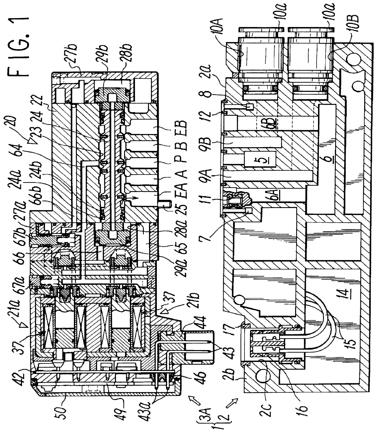
FIG. 1 shows a first embodiment, disassembled, of a sealed transfer valve assembly according to this invention. A sealed transfer valve assembly 1 is composed of a divided manifold 2 for each transfer valve and a solenoid-operated pilot transfer valve 3A mounted on a valve mounting surface 2a of manifold 2.

Manifold 2 comprises a supply channel 5 and an ejection channel 6 for a pressure fluid formed in the manifold connection direction (perpendicular to the plane of the drawing), and an external pilot supply channel 7 and external pilot ejection channel 8 used to introduce a pilot fluid from the exterior. Supply channel 5, pilot supply channel 7, and pilot ejection channel 8 are all opened to valve mounting surface 2a, while ejection channel 6 opens to valve mounting surface 2a at two positions through channels 6A and 6B.

Output channels 9A and 9B for a pressure fluid communicate with openings in valve mounting surface 2a and with output ports 10A and 10B on the front surface of manif...

second embodiment

FIG. 4 shows the transfer valve in the sealed transfer valve assembly according to this invention. Transfer valve 3B is a single-pilot type having a single-pilot valve 21a, shaped similarly to transfer valve 3A, using as many parts as possible in common with transfer valve 3A.

Main valve 20B in transfer valve 3B has substantially the same configuration as main valve 20 in the first embodiment, except that second piston chamber 28b and second piston 29b have smaller diameters than first piston chamber 28a and second piston 29a, and that second piston chamber 28b communicates directly with pilot supply passage 64 through pilot output passage 66. Thus, analogous components in the figure bear the same reference numbers. Their description is omitted.

In addition, one valve opening and closing section 30 is integrated into pilot valve body 32, and one solenoid 31 and one dummy member 70 are integrated into solenoid section 33. That is, in solenoid section 33, one coil assembly 37 and dummy ...


PUM


Abstract

A sealing article 17 is provided in the opening edge of a depression 2c provided in a manifold 2 to connect a supply connector 16 and a receiving connector 44 in an air-tight manner. A solenoid section 33, in which a solenoid 31 in each of pilot valve 21a and 21b and a receiving connector 44 that supplies power to connector 31 are sealed into a synthetic resin 45, is provided in a transfer valve 3A. Solenoid section 33 has a lamp circuit board 49 mounted on its outer surface to receive power from receiving connector 44, and includes power supply indicator lamps 48; and a cover 50, covering the whole of lamp circuit board 49, mounted to form an air-tight seal on its outer surface via a gasket 52.

Description

The present invention relates to a sealed transfer valve assembly that provides improved insulating capabilities by creating an air-tight seal of electrical connections.PRIOR ARTCommonly-used techniques provide for a transfer valve assembly that couples a solenoid-operated pilot transfer valve, in which a solenoid-operated pilot valve operates a main valve for switching channels for an operating fluid, to a manifold for supplying operating fluid and power to the transfer valve.In such a transfer valve assembly, when an electrical connection that supplies power to the solenoid in a pilot valve, or a mounting portion for electrical parts such as power supply indicator lamps, is left exposed, its insulating capabilities may deteriorate if the transfer valve operates in a humid environment, resulting in leakage or open circuits. Such deterioration leads to hazardous conditions.As one example of efforts to find a solution to this difficulty, Japanese Patent Application Laid Open No. 4-27...

Claims


Application Information

Patent Timeline
Patent Type & Authority Patents(United States)
IPC IPC(8): F15B13/00F15B13/08F16K27/00F16K31/06H02G3/22
CPCF15B13/0817F15B13/0828F15B13/0839F15B13/0853F15B13/0857F15B13/0864F15B13/0867Y10T137/86614Y10T137/8376Y10T137/87885Y10T137/8158F16K31/00
Inventor KANEKO, RYUSHIROISHIKAWA, MAKOTONARITA, MASARU
Owner SMC CORP
Why Eureka
Try Eureka