Ultrasonic vibration bonding resonator

a resonator and ultrasonic technology, applied in the field of resonators, can solve the problems of reducing the bonding function area of the resonator, affecting the quality of the resonator, and requiring a great deal of labor and time for reassembling and re-tuning the resonator

Inactive Publication Date: 2000-08-29
ULTEX CORP
View PDF10 Cites 39 Cited by
  • Summary
  • Abstract
  • Description
  • Claims
  • Application Information

AI Technical Summary

Problems solved by technology

However, the bonding function area of the resonator is worn down by diffusion caused by bonding temperature.
If the surface profile of the bonding function area of the resonator becomes rough by such repeated wear, a bonding failure of the bonded members may occur or a bonding flaw may be produced on the surface of the bonded members, thereby leading to lack of quality and reliability.
However, the resonator must be removed from the apparatus for repair, and reassembling and re-tuning of the resonator require a great deal of labor and time.
In addition, a polishing margin of the bonding function area can not be secured sufficiently to obtain an appropriate resonance state.
The resonator therefore can not be used any longer after several repairs and quite uneconomical for the user.
Also, since the bonding function area is too short to carry out an effective bonding operation on the inside of a workpiece having a box-like shape because the workpiece is quite deep.

Method used


Image

  • Ultrasonic vibration bonding resonator
  • Ultrasonic vibration bonding resonator
  • Ultrasonic vibration bonding resonator

Examples


first embodiment

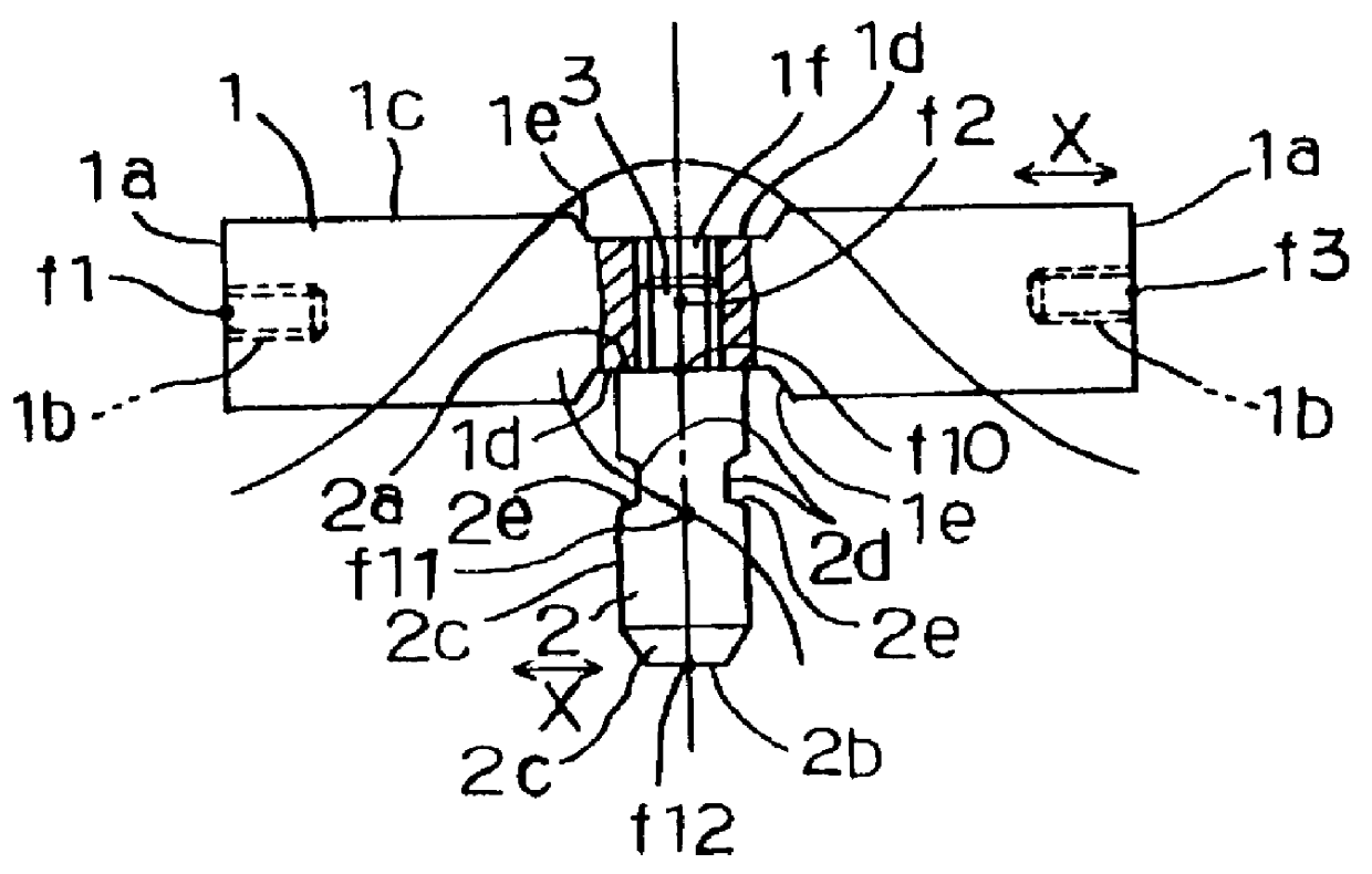
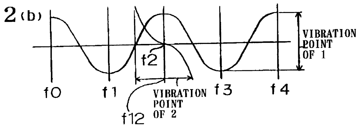
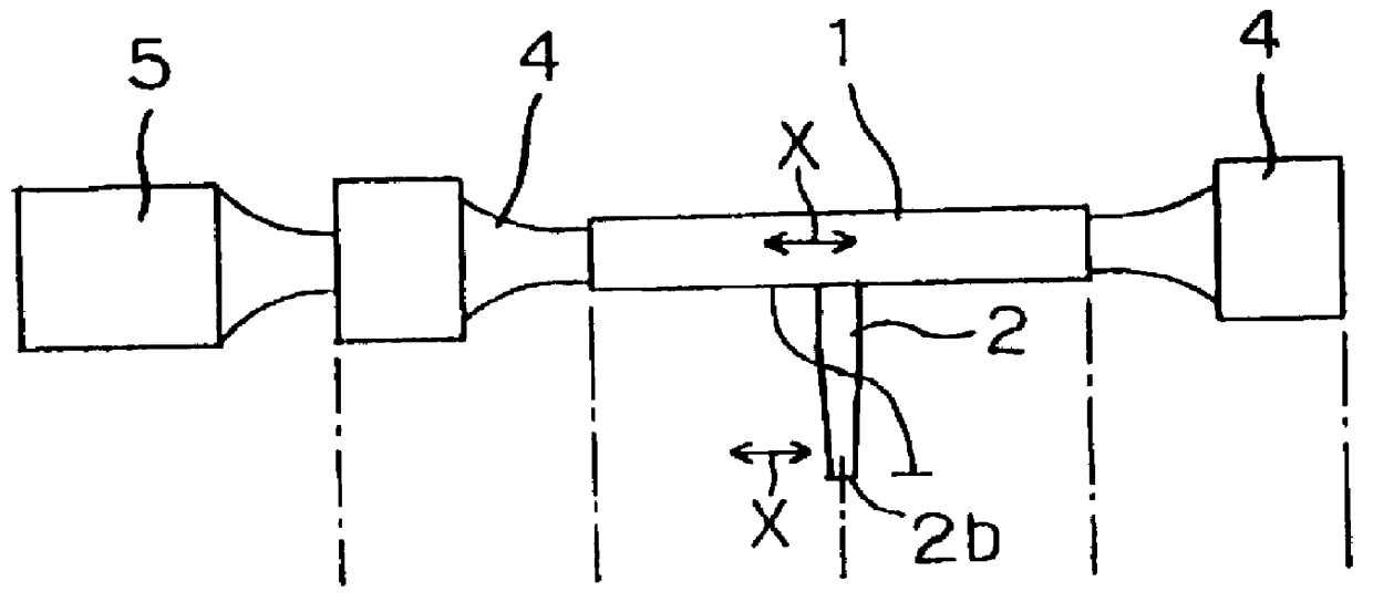
FIGS. 1-3 show the present invention. FIG. 1 is a side view wherein an ultrasonic horn 1 and a bonding tool 2 are connected together by a screw member 3. FIG. 2(a) is a side view wherein a booster 4 and an oscillator 5 are added to the elements of FIG. 1 and FIG. 2(b) shows a vibration wave corresponding to FIG. 2(a). FIG. 3 is a front view showing an ultrasonic bonding apparatus wherein the elements shown in FIG. 2 are added.

In FIG. 1, the ultrasonic horn 1 forming the resonator body is made of one material selected from aluminum, iron, titanium and the like, in a bar shape, and The oscillator is coaxially connected to one end of the ultrasonic horn directly or indirectly through the booster (not shown). This oscillator is an electro-acoustic transducer or electric oscillation transducer consisting of a piezoelectric element, magnetostrictor or the like for transducing electric energy to mechanical energy. The electric energy is output by generating ultrasonic vibration of longitud...

second embodiment

FIG. 4 shows a side of a bonding tool 2A according to the second embodiment. The bonding tool 2A has a length equivalent to the wavelength of the resonance frequency. It also has the maximum vibration amplitude point at the base end surface 2a and the top end surface 2b. A screw member 3 is provided with a male screw outside the base end surface 2a in the axial direction and arranged to project from the base end surface 2a. The bonding tool 2A is also designed to be further distant from the ultrasonic horn 1 compared with the bonding tool 2 of the first embodiment. Thus, effective bonding can be performed on various workpieces (bonded members) merely by replacing the bonding tool 2 of the first embodiment with the bonding tool 2A of the second embodiment.

third embodiment

FIG. 5 shows the relationship between bonding tools 2B, 2C and 2D and screw members 3A, 3B and 3C according to a third embodiment of the present invention. In FIG. 5(a), the bonding tool 2B has a threaded hole 2f provided with a female screw at a base end surface 2a. The screw member 3A is a headless screw, wherein a half portion of the screw member 3A is threaded into the threaded hole 2f and another half portion thereof coaxially projects from the bonding tool 2B in a straight line. In FIG. 5(b), the bonding tool 2C is provided with a round bar which projects coaxially from the base end surface 2a and integrally formed with the bonding tool 2C. The round bar is also provided with a male screw at the periphery and the bonding tool 2c is provided with the screw member 3B. In FIG. 3(c), a guard 6 is formed between the bonding tool 2D and the screw member 3C. Namely, as far as the relationship between the bonding tools 2B, 2C and 2D and the screw members 3A, 3B and 3C is concerned, an...


PUM

PropertyMeasurementUnit
lengthaaaaaaaaaa
resonanceaaaaaaaaaa
resonance frequencyaaaaaaaaaa

Abstract

In order to realize effective and economical bonding operation even on workpiece whose inside is quite deep, a bonding tool, which has a length equivalent to a whole number of multiples of half the wavelength of the resonance frequency, is secured to an ultrasonic horn by a screw member which can advance or retreat in a direction perpendicular to the vibration direction indicated by an arrow X,thereby causing a front end surface of the bonding tool vibrate in the same direction as the vibration of the ultrasonic horn.

Description

1. Field of the InventionThe present invention relates to a resonator used in a bonding apparatus for overlapped bonded members by ultrasonic vibration2. Description of the Prior ArtAs disclosed in Japanese Published Patent Application No. Sho 54-13349, it is known that an ultrasonic vibration bonding apparatus is provided with a resonator connected to an oscillator for generating ultrasonic vibration and a mount for mounting overlapped bonded members thereon and holding these members under pressure between this mount and the resonator, wherein an interface of the overlapped bonded members is bonded by transmitting the ultrasonic vibration from the oscillator to the resonator.The resonator used in such an ultrasonic vibration bonding apparatus is made through the following process. Materials for the resonator are cut to a shape and size determined by the materials, thickness and shape of the bonded members, oscillation output of the oscillator and the like to make a primarily proces...

Claims


Application Information

Patent Timeline
Patent Type & Authority Patents(United States)
IPC IPC(8): B23K20/10B06B1/02
CPCB23K20/106
Inventor SATO, SHIGERU
Owner ULTEX CORP
Why Eureka
Try Eureka