Hot water-type heating device

a heating device and hot water technology, applied in vehicle heating/cooling devices, heat exchange apparatuses, vehicle components, etc., can solve the problems of increasing the number of components, the size of the valve device portion of the hot water-type heating device becomes large, and the corresponding increase in cost cannot be prevented

Inactive Publication Date: 2000-08-29
DENSO CORP
View PDF12 Cites 17 Cited by
  • Summary
  • Abstract
  • Description
  • Claims
  • Application Information

AI Technical Summary

Problems solved by technology

In the related art described above, however, because a variable restricting valve other than the pressure-responsive valve is additionally disposed with respect to the flow control valve, a size of the valve device portion of the hot water-type heating device becomes large and the n

Method used


Image

  • Hot water-type heating device
  • Hot water-type heating device
  • Hot water-type heating device

Examples


first embodiment

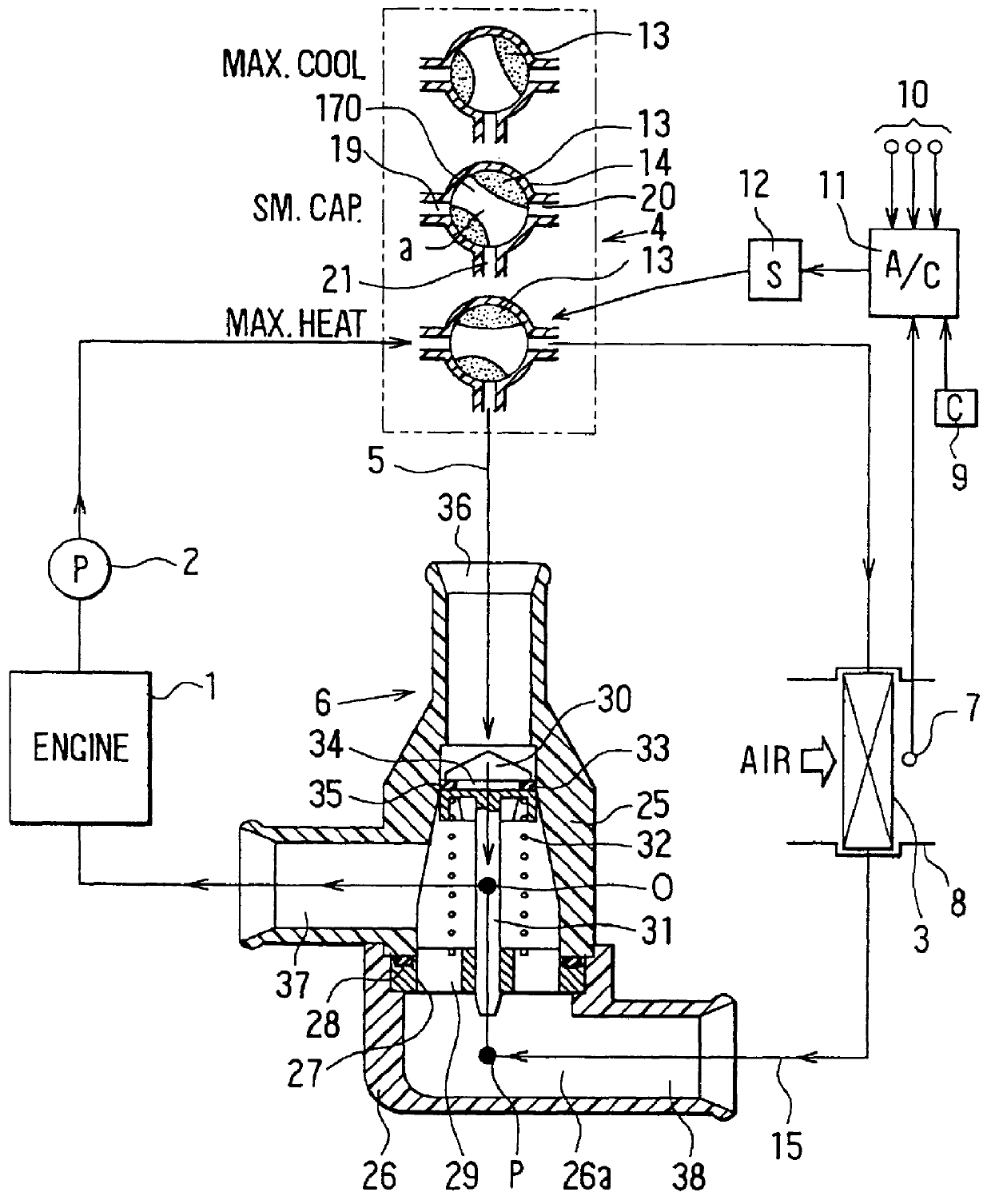
FIG. 1 shows the present invention as applied to a hot water-type heater apparatus of an air conditioning device for automotive use. Reference numeral 1 denotes a water-cooled type engine for automotive use; 2 denotes a water pump driven by the engine 1 to circulate water in a coolant water circuit (hot water circuit) of the engine 1; 3 denotes a heat exchanger for use as a heater core to exchange heat between hot water supplied from the engine and blown air to thereby heat the blown air; 4 denotes a flow control valve according to the present invention and is a three-way type flow control valve having three hot water inlets / outlets.

Reference numeral 5 denotes a bypass circuit disposed with the heat exchanger 3 in parallel, and 6 denotes a constant differential pressure valve (pressure-responsive valve) which opens when the differential pressure between its sides reaches a previously established specified value and which makes the inlet and outlet pressures of the heat exchanger 3 s...

second embodiment

(Second Embodiment)

In the first embodiment in FIG. 1, although the merging portion "O" between the bypass side hot water and the returning hot water from the heat exchanger 3 is disposed at the middle portion (the middle portion of the coil spring 32) between the valve body 30 of the constant differential pressure valve 6 and the seating plate 27, in a second embodiment shown in FIG. 3, members of the constant differential pressure valve 6 are all held in the housing 25 in the upper side, so that the merging portion "O" is disposed in the downstream side below the seating plate 27 of the constant differential pressure valve 6. That is, in the second embodiment, the merging portion "O" and the curving point P are positioned in the housing 26 in the lower side.

In the second embodiment, compared to the first embodiment, the position of the merging portion "O" is far away from the valve body 30 of the constant differential pressure valve 6, so that the fact that dynamic pressure generat...

third embodiment

(Third Embodiment)

In the first and the second embodiments, the bypass side hot water and the returning hot water from the heat exchanger 3 are merged from the different directions in which one direction is shifted by 180.degree. from the other. On the other hand, in the third embodiment shown in FIG. 4, the hot water flow passage in the housing 26 in the lower side is formed linearly toward the outlet 37 from the inlet 38 and the bypass side hot water can merge from a perpendicular direction with respect to the flow of the returning hot water from the heat exchanger 3.

According to the third embodiment, because the bypass side hot water merges from the perpendicular direction with respect to the flow of the returning hot water from the heat exchanger 3, compared with the first and second embodiments, the blocking operation of the flow of the returning hot water is reduced; however, compared with a case when the flow of the returning hot water and the bypass side hot water merge in pa...


PUM


Abstract

To control fluctuation of blown air temperature of a heat exchanger to a small value without adding a movable mechanism such as a variable restricting valve, a heat exchanger for heating air by exchanging heat between hot water supplied from a water-cooling type engine and air, a flow control valve for controlling a hot water flow amount to the heat exchanger and a bypass circuit for allowing hot water to flow while bypassing the heat exchanger are provided. A pressure-responsive valve is provided on the bypass circuit and an opening degree of the bypass circuit corresponding to a pressure rise of the hot water is increased. The flow of returning hot water from the heat exchanger is blocked by the flow of the bypass side hot water at a merging portion where the bypass side hot water discharged from the pressure-responsive valve merges with the returning hot water discharged from the heat exchanger.

Description

This application is related to Japanese Patent Application No. Hei 8-191012, incorporated herein by reference.1. Field of the InventionThe present invention relates to heating devices, and particularly relates to a heating device which uses hot water to adjust the temperature of air blown into a vehicle passenger compartment by controlling the amount of hot water flowing therein using a flow control valve.2. Description of Related ArtA method in which blown air temperature is controlled by controlling a flow amount of hot water to a heat exchanger is known in the art. In such an automotive air conditioner, a water pump driven by the automobile engine is used in a hot water circuit in which the hot water (engine cooling water) is circulated. Therefore, the rotational speed of the water pump fluctuates with fluctuations of engine rotational speed and hot water pressure to the heat exchanger fluctuates to a large degree. Because the fluctuation is a factor of fluctuation of the tempera...

Claims


Application Information

Patent Timeline
IPC IPC(8): B60H1/00F28F27/00F28F27/02B60H1/08
CPCB60H1/00485B60H1/00878F28F27/02
Inventor ITO, KOICHIOKUMURA, YOSHIHIKOINOUE, YOSHIMITSUSUGI, HIKARU
Owner DENSO CORP
Why Eureka
Try Eureka