Apparatus and method to cool a bearing in a centrifugal separator

a centrifugal separator and bearing technology, applied in the direction of bearings, bearing components, rotary machine parts, etc., can solve the problems of difficult to provide the fan, significant complexity, and difficult to obtain a sufficient cooling capacity

Inactive Publication Date: 2000-09-12
ALFA LAVAL AB
View PDF8 Cites 32 Cited by
  • Summary
  • Abstract
  • Description
  • Claims
  • Application Information

AI Technical Summary

Problems solved by technology

However, such a fan requires space and therefore it may be difficult to provide the fan in the proximity of the bearing.
In addition, the fan causes a significant complexity with respect to the sealing against other spaces of the centrifugal separator and against the

Method used


Image

  • Apparatus and method to cool a bearing in a centrifugal separator
  • Apparatus and method to cool a bearing in a centrifugal separator
  • Apparatus and method to cool a bearing in a centrifugal separator

Examples


Embodiment Construction

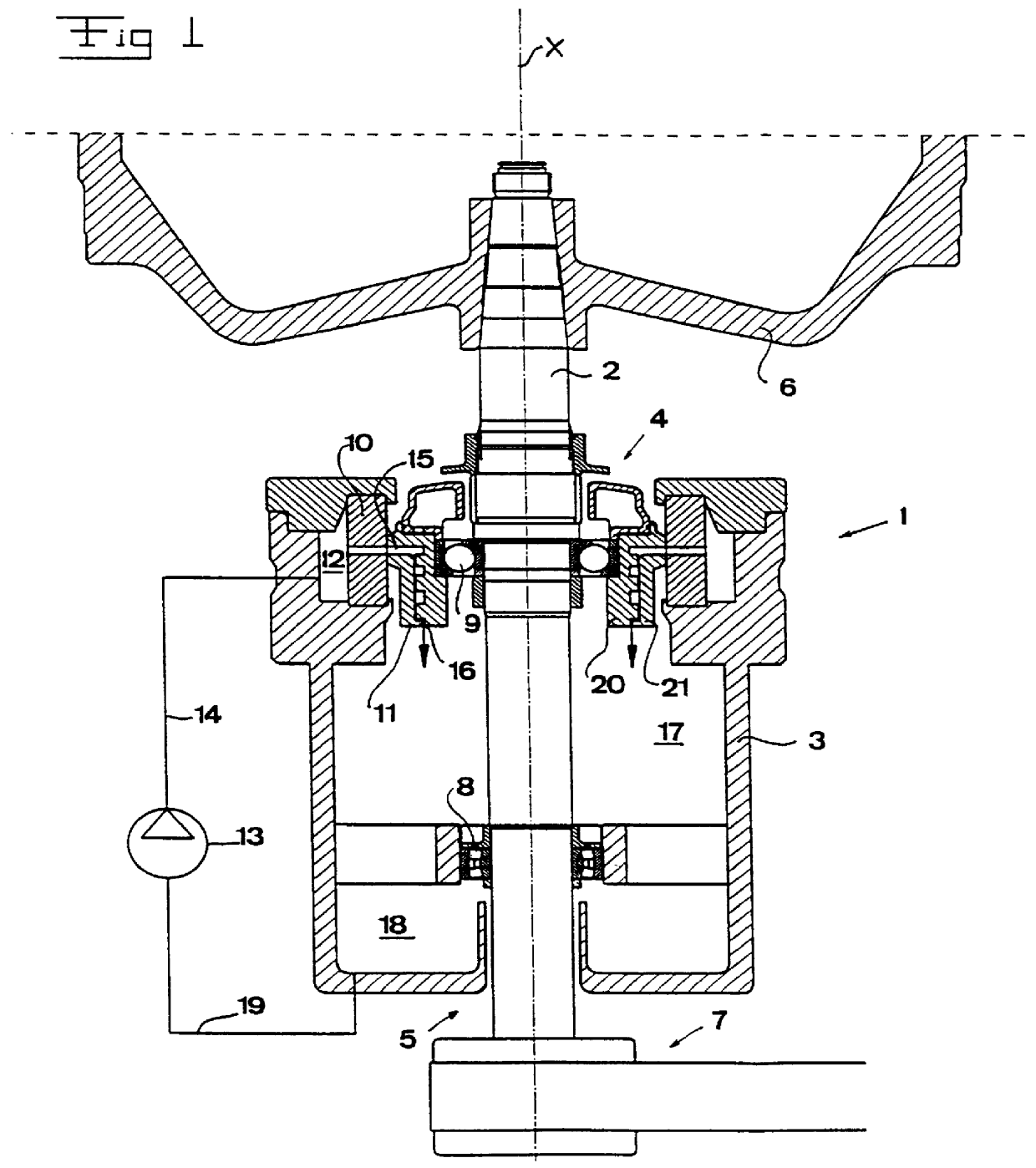
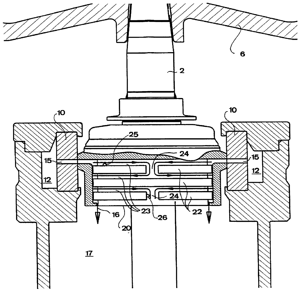
The shaft support unit 1 disclosed in FIG. 1 carries a shaft 2 of the centrifugal separator, which is arranged to rotate about a rotational axis x. The shaft support unit 1 has an outer casing 3 enclosing the shaft 2. In the axial end portions of the outer casing 3, two apertures 4 and 5, respectively, are provided, through which the shaft 2 extends. A centrifugal rotor 6 is fixedly attached to one axial end of the shaft 2 and a belt drive device 7 is provided on the other axial end for driving the shaft 2 and the centrifuge rotor 6. The shaft 2 is journalled in a lower bearing 8, which is essentially directly connected to the outer casing 3, and in an upper bearing 9 which is connected to the outer casing 3 via an annular elastic element 10 and a bearing housing 11. The elastic element 10 forms together with the outer casing 3 a chamber 12 extending around the shaft 2 radially outside the elastic element 10.

In accordance with the present invention, the shaft support unit 1 comprise...


PUM


Abstract

The invention refers to a device and a method for cooling a bearing of a centrifugal separator. Through a portion (11, 21) adjacent to the bearing extends at least one channel (15, 23), which is arranged to receive a flow of a cooling medium and comprises at least two successive channel portions (23) and at least one connecting portion (24) provided between successive channel portions. The connecting portion (24) is arranged to provide such a mixing of the cooling medium in the flow through the channel that the flow has an essentially uniform velocity profile immediately after the connecting portion.

Description

THE BACKGROUND OF THE INVENTION AND PRIOR ARTThe present invention refers to a device for cooling a bearing of a centrifugal separator, comprising a portion adjacent to the bearing and at least one channel, which extends through this portion, is arranged to receive a flow of a cooling medium and comprises at least two successive channel portions and at least one connecting portion provided between successive channel portions. Moreover, the invention refers to a method of cooling a bearing of a centrifugal separator, wherein a cooling medium is conveyed in a flow through at least one channel, which is provided in a portion adjacent to the bearing and comprises at least two channel portions successively provided.The cooling of bearings of centrifugal separators has traditionally involved an internally recirculating air stream absorbing the heat in the actual bearing and giving off the heat to other parts of the centrifugal separator, for instance the inner side of the wall of the supp...

Claims


Application Information

Patent Timeline
IPC IPC(8): B04B9/00B04B9/12F16C37/00B04B15/02
CPCB04B9/12F16C37/007F16C2300/34
Inventor SZEPESSY, STEFANPITKAMAKI, JOUKO JUHANI
Owner ALFA LAVAL AB
Why Eureka
Try Eureka