Color cathode ray tube

a cathode ray tube and color technology, applied in the direction of cathode ray tubes/electron beam tubes, electric discharge tubes, electrical apparatus, etc., can solve the problems of reduced light illuminance, reduced so-called color purity, and narrow phosphor layers. achieve excellent color purity

Inactive Publication Date: 2000-09-26
KK TOSHIBA
View PDF3 Cites 12 Cited by
  • Summary
  • Abstract
  • Description
  • Claims
  • Application Information

AI Technical Summary

Benefits of technology

The present invention has been conceived to solve the above-mentioned problems, and its object is to provide a color cathode ray tube having excellent color purity by eliminating the phenomenon wherein phosphor layers in the form of stripes are narrowed.

Problems solved by technology

However, when phosphor layers in three colors are printed by applying the shadow mask as described above to a flat tube wherein the effective region of the panel is nearly planar and a deflection angle is about 110.degree., a phenomenon occurs wherein phosphor layers become undesirably narrow in the vicinity of the ends of diagonal axes of the panel effective region where illuminance of the light from the exposing device is lowest.
When phosphor layers in the vicinity of the end portions of the diagonal axes are narrowed as described above, brightness is lowered in the vicinity of the corners of the display screen to give dark appearance, which results in a problem in that the so-called color purity is reduced.

Method used


Image

  • Color cathode ray tube
  • Color cathode ray tube
  • Color cathode ray tube

Examples


Embodiment Construction

A color cathode ray tube according to an embodiment of the invention will now be described in detail with reference to the drawings.

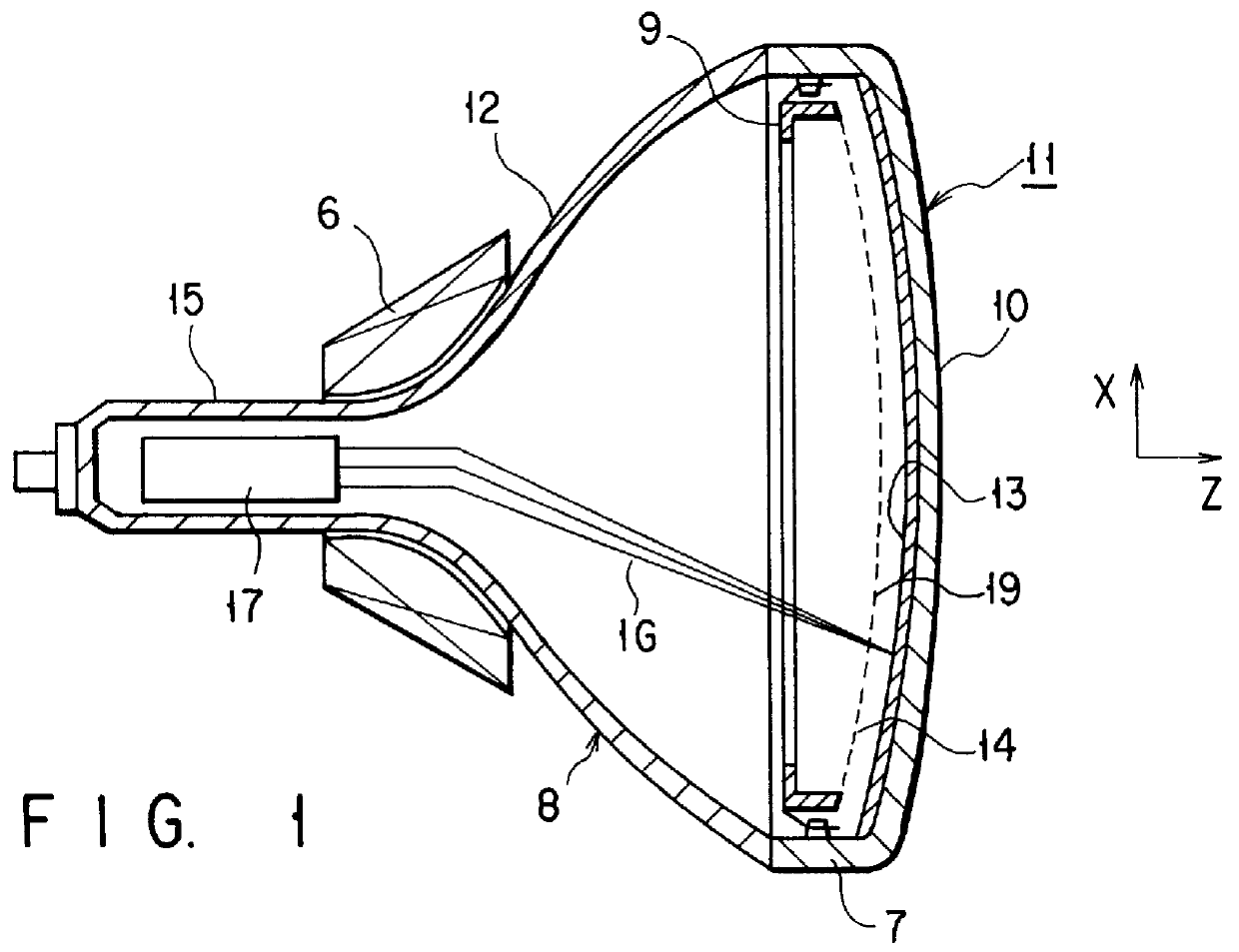
Referring to FIG. 1, the color cathode ray tube includes a vacuum envelope 8 having a face panel 11 and a funnel 12. The face panel 11 includes a substantially rectangular effective portion 10 which is constituted by a curved surface, and a skirt portion 7 erected on the periphery of the effective portion. The funnel 12 is connected to the skirt portion 7.

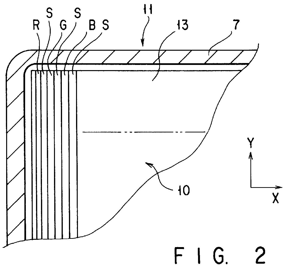
A phosphor screen 13 is formed on an inner surface of the effective portion 10 of the face panel 11. As shown in FIG. 2, the phosphor screen 13 is constituted by phosphor layers in three colors R, G, and B in the form of elongate stripes which emit blue, green and red beams of light and which extend in a vertical direction Y. Shading layers S in the form of stripes are formed between the phosphor layers.

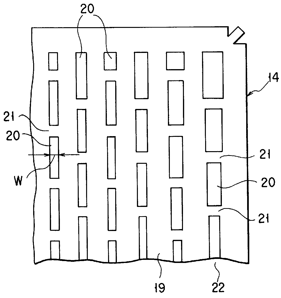
A substantially rectangular shadow mask 14 is disposed in the vacuum envelope 8 to face the phosphor...


PUM


Abstract

PCT No. PCT / JP97 / 03994 Sec. 371 Date Jul. 2, 1998 Sec. 102(e) Date Jul. 2, 1998 PCT Filed Oct. 31, 1997 PCT Pub. No. WO98 / 20514 PCT Pub. Date May 14, 1998A shadow mask disposed to face a phosphor screen of a cathode ray tube includes a substantially rectangular effective surface on which a number of substantially rectangular apertures are formed. The effective surface has horizontal and vertical axes which perpendicularly cross in the center thereof and diagonal axes passing through the center. The apertures are arranged to form a plurality of vertical rows of apertures extending in the direction of the vertical axis. Each of the vertical rows of apertures includes a plurality of apertures arranged in the direction of the vertical axis with a bridge portion being interposed between two adjacent apertures, and those vertical rows of apertures are arranged in the direction of the horizontal axis at a predetermined pitch. The width W of the apertures in the direction of the horizontal axis is formed so as to gradually increase from that of the aperture located at the center of the effective surface to that of the apertures located at the peripheries of the effective surface in the direction of the horizontal axis. The width of each of corner apertures located in the vicinity of the ends of the diagonal axes is larger than the width of the aperture located on the horizontal axis in the same vertical row of apertures to which the corner aperture belongs.

Description

The present invention relates to a color cathode ray tube and, more particularly, to a color cathode ray tube including a shadow mask having a number of rectangular apertures as apertures for transmitting electron beams.In general, a color cathode ray tube includes an envelope having a substantially rectangular panel, a phosphor screen formed of phosphor layers, emitting three colors, formed on the inner surface of an effective region of the panel, and a substantially rectangular shadow mask disposed inside the phosphor screen in a face-to-face relationship. A multiplicity of apertures serving as electron beam passage apertures are formed in an effective surface of the shadow mask in a predetermined arrangement. Three electron beams emitted from an electron gun disposed in a neck of the envelope impinge upon predetermined phosphor layers according to selection performed by the shadow mask, thereby displaying a color image.In such a color cathode ray tube, each of the apertures in th...

Claims


Application Information

Patent Timeline
Patent Type & Authority Patents(United States)
IPC IPC(8): H01J29/07
CPCH01J29/07H01J29/076H01J2229/075H01J2229/0772H01J2229/0788
Inventor SHODA, AKIRA
Owner KK TOSHIBA
Why Eureka
Try Eureka