

Precision drill bit
a drill bit, precision technology, applied in the direction of twist drills, manufacturing tools, wood boring tools, etc., can solve the problems of cumbersome two-step process, cumbersome time and labor, and sloppy drilling operations of hand-held or less rigid drilling operations, so as to reduce friction on the drill body, increase the life of the drill, and accelerate the drilling of cylindrical holes
- Summary
- Abstract
- Description
- Claims
- Application Information
AI Technical Summary
Benefits of technology
Problems solved by technology
Method used
Image

Examples
Embodiment Construction
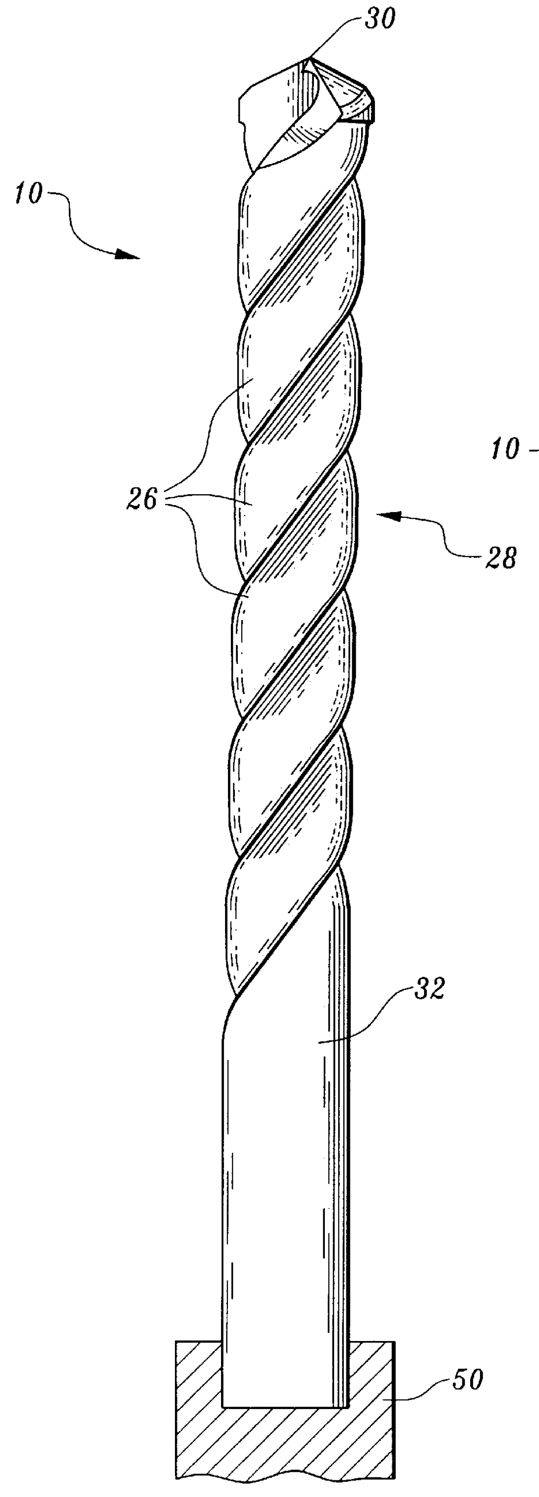
Considering the drawings, wherein like reference numerals denote like parts throughout the various drawing figures, reference numeral 10 is directed to the drill according to the present invention.
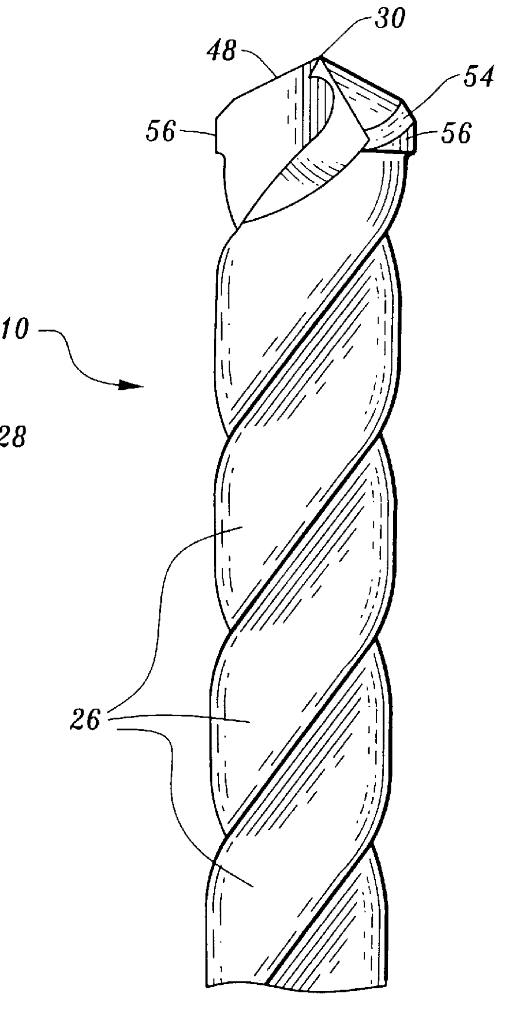
Referring now to FIGS. 1 and 2, a shank 32 is received and mounted by turning device 50. Thereafter the shank 32 transitions into a body 28 of the drill 10. Body 28 is helically transposed about flute 26. Flute 26 is a channel for removing chips or curls from the work surface and / or allowing lubricants or coolants to reach the tip of the drill 10. A leading edge of flute 26 at margin 56 forms a cutting lip 48 which, when taken toward the tip of the drill, transitions into an orientation surface 54. That orientation surface 54 will aid a drill operator in orienting the drill bit 10 only in a manner which will cause a cylindrical hole to be formed and provide better cutting reaction at or near the chisel edge 34 (FIG. 4). Furthermore, margin 56, extending only a short portion down the flutes...
PUM
| Property | Measurement | Unit |
|---|---|---|
| subtended angle | aaaaa | aaaaa |
| angle | aaaaa | aaaaa |
| inclination angle | aaaaa | aaaaa |
Abstract
Description
Claims
Application Information