Switching power supply unit

a power supply unit and power supply technology, applied in the direction of power conversion systems, dc-dc conversion, instruments, etc., can solve the problems of increasing production costs, complicated circuit structure, and increasing the number of parts, so as to increase the size and weight of the increase in the number of parts

Inactive Publication Date: 2000-10-10
MURATA MFG CO LTD
View PDF7 Cites 15 Cited by
  • Summary
  • Abstract
  • Description
  • Claims
  • Application Information

AI Technical Summary

Problems solved by technology

In this way, when an IC, a pulse transformer, or the like is used, the circuit structure is complicated and production cost i

Method used


Image

  • Switching power supply unit
  • Switching power supply unit
  • Switching power supply unit

Examples


first embodiment

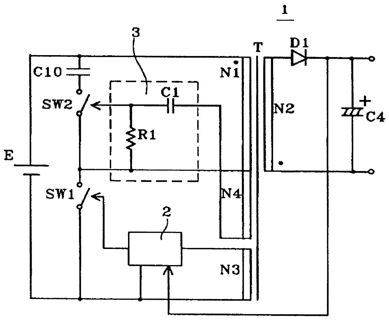
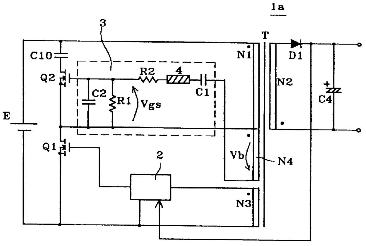
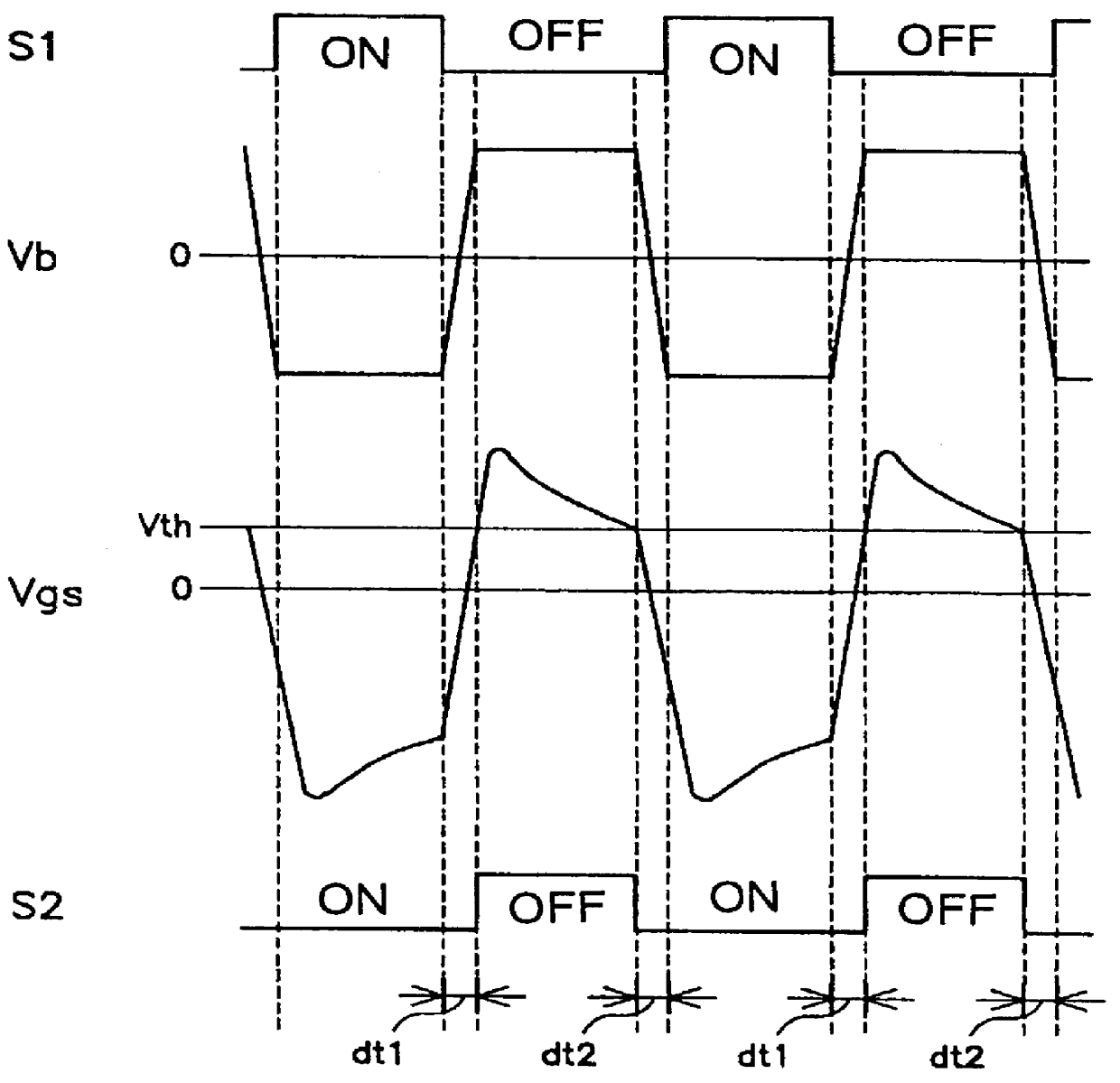
In FIG. 2, reference numeral 1a indicates a switching power supply unit in accordance with a This adopts an active clamp system in the application circuit of a fly-back converter, in which a surge voltage to the main switching element is clamped.

The switching power supply unit 1a has a DC power supply E and a transformer T. The DC power supply E may be obtained by rectifying and smoothing an AC input. In addition, the transformer T has a primary winding N1, a secondary winding N2, a main switching element drive winding (hereinafter referred to as a first drive winding) N3, and an auxiliary switching element drive winding ((hereinafter referred to as a second drive winding) N4.

In addition, a field-effect transistor (hereinafter referred to as an FET) Q1 as the main switching element, the primary winding N1 of the transformer T, and the DC power supply E are connected in series, and a field-effect transistor (FET) Q2 as the auxiliary switching element, and a capacitor C10 are connect...

second embodiment

Referring to FIG. 12, a description will be given of the structure of a switching power supply unit according to the present invention. In this figure, the same parts as those in FIG. 2 or the equivalent thereto are given the same reference numerals and the explanation thereof is omitted.

In FIG. 12, reference numeral 11 indicates a switching power supply unit, which is ordinarily referred to as a forward converter, specifically, which adopts the so-called synchronous rectification system, in which rectification is performed by using two auxiliary switching elements disposed on the secondary side of a transformer. In the switching power supply unit 11, a main switching element repeatedly performs alternate ON / OFF operations, and when it is ON, power is supplied to a load.

The switching power supply unit 11 comprises a transformer T1, an FET Q11 as a main switching element, an FET Q21 and an FET Q22 as auxiliary switching elements, a main control circuit 2 for controlling the ON / OFF op...


PUM


Abstract

A switching power supply unit providing a DC output comprises a DC power supply; a transformer having a primary winding; a main switching element for connecting in series to the primary winding; and an auxiliary switching element for performing ON/OFF operations in synchronism with or opposite to ON/OFF operations performed by the main switching element; wherein an auxiliary switching element drive winding for generating a voltage turning on/off the auxiliary switching element is disposed in the transformer; and a first impedance circuit including a first resistor, a first capacitor being connected in series with the first impedance circuit, and a differentiating circuit for determining the timing for turning on the auxiliary switching element and the ON time thereof is connected to the auxiliary switching element drive winding.

Description

1. Field of the InventionThe present invention relates to a switching power supply unit having a main switching element and a single or a plurality of auxiliary switching elements which perform ON / OFF operations in synchronism with or opposite to ON / OFF operations of the main switching element.2. Description of the Related ArtIn general, in electronic equipment such as electronic calculators and communication devices, a switching power supply unit has been widely used for supplying a stabilized DC voltage from a commercial AC power supply. As the switching power supply unit, there are provided switching power supply units having different circuit systems, such as a forward converter, or a fly-back converter, in which a main switching element, which is connected in series to a primary winding of a transformer, is repeatedly turned on / off to intermittently apply an input voltage to the transformer so as to obtain a DC output through a rectifying and smoothing circuit connected to a se...

Claims


Application Information

Patent Timeline
IPC IPC(8): H02M3/24H02M3/338H02M3/28
CPCH02M3/3385
Inventor HOSOTANI, TATSUYA
Owner MURATA MFG CO LTD
Why Eureka
Try Eureka