Method of manufacturing an encapsulated transducer with an integrally formed full length sleeve and a component alignment preform

a technology of encapsulation and transducer, which is applied in the direction of magnetic bodies, semiconductor/solid-state device details, instruments, etc., can solve the problem of difficult replacement of such transducers

Inactive Publication Date: 2000-10-17
BENTLY NEVADA INC
View PDF40 Cites 19 Cited by
  • Summary
  • Abstract
  • Description
  • Claims
  • Application Information

AI Technical Summary

Benefits of technology

Another further object of the present invention is to provide an encapsulated transducer as characterized above wherein the encapsulation strongly bonds to the sleeved coil and cable assembly for providing a leak tight seal and resisting axial forces applied to the encapsulation or cable which may cause the electrical connections to completely or partially break resulting in an inoperative or unreliable transducer.
Another further object of the present invention is to provide an encapsulated transducer as characterized above which is capable of being mass produced with reproducible operational characteristics without appreciable alterations of the signals they admit when in operation.

Problems solved by technology

In this environment, the transducer must operate under very adverse physical, chemical and mechanical conditions and it is often very difficult to replace such transducers.

Method used


Image

  • Method of manufacturing an encapsulated transducer with an integrally formed full length sleeve and a component alignment preform
  • Method of manufacturing an encapsulated transducer with an integrally formed full length sleeve and a component alignment preform
  • Method of manufacturing an encapsulated transducer with an integrally formed full length sleeve and a component alignment preform

Examples


Embodiment Construction

Considering the drawings, wherein like reference numerals denote like parts throughout the various drawing figures, reference numeral 10 is directed to the encapsulated transducer with a component alignment preform according to the present invention.

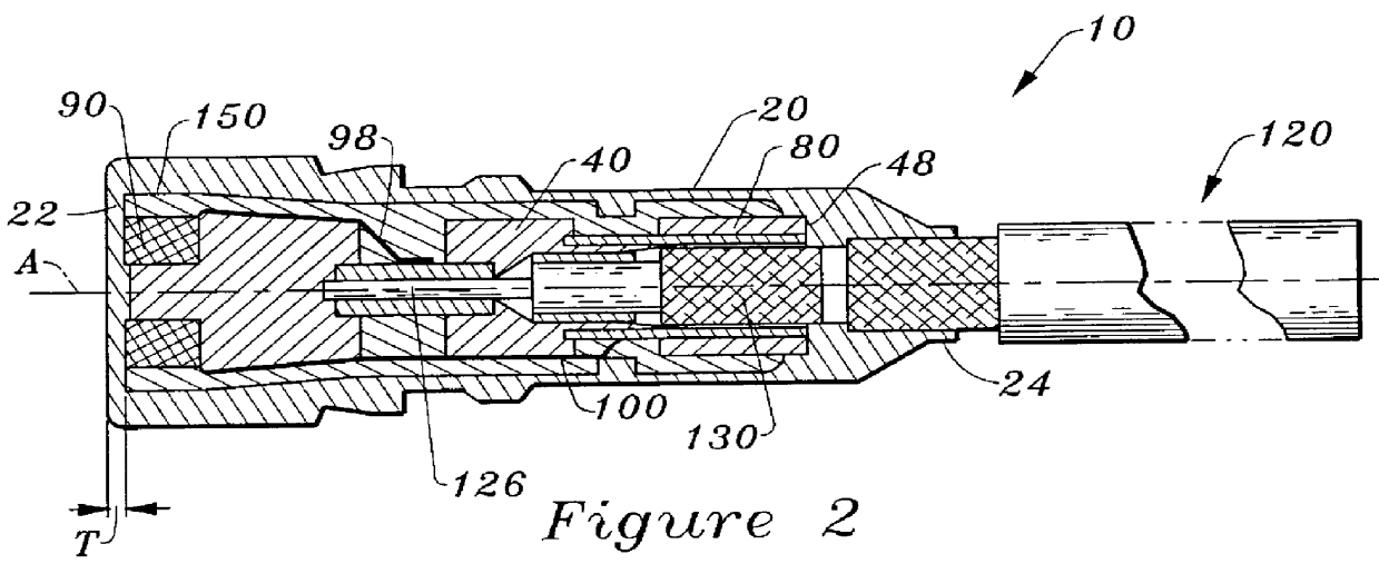
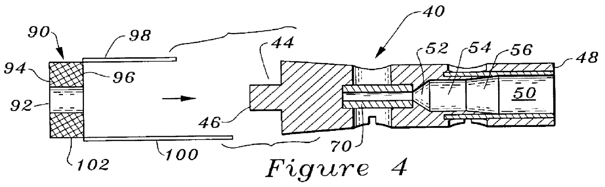
In essence, and referring to FIGS. 2 and 6, the encapsulated transducer 10 includes an injection molded encapsulation 20 having a front end 22 and a back end 24. The encapsulation 20 is a monolith of cured moldable material ensconcing a sensing element 90 proximate the front end 22 and a portion of an information transmitting medium 120 emanating from the back end 24. A component alignment preform 40 operatively couples the sensing element 90 with the information transmitting medium or cable 120. The component alignment preform 40 includes a front ferrule 70 and a rear ferrule 80 bonded thereto and linearly spaced apart along a long axis "A". The component alignment preform 40 further includes an annular recess 44 (FIG. 3) in which the s...


PUM

PropertyMeasurementUnit
diameteraaaaaaaaaa
electricallyaaaaaaaaaa
lengthaaaaaaaaaa

Abstract

An encapsulated transducer (10) includes an injection molded encapsulation (20) having front end (22) and back end (24). The encapsulation (20) is a monolith of cured moldable material ensconcing a sensing element or coil (90) proximate front end (22) and a portion of an information transmitting medium (120) emanating from back end (24). A component alignment preform (40) operatively couples sensing element (90) with information transmitting medium (120). A protective sleeve (150) is transfer molded over coil (90) and interlocked with preform (40) thereby forming a sleeved coil and cable assembly (170). This sleeved coil and cable assembly (170) is encapsulated by an injection molding process which provides the durable encapsulation (20). The sleeved coil and cable assembly (170) is symmetrically disposed within the encapsulation (20) and the encapsulation (20) includes an integrally formed protective wall having a uniform thickness "T" along a forwardmost portion of sensing element (90) and integrally transitioning into an uninterrupted side wall circumscribing the sensing element and a portion of the cable.

Description

The present invention relates generally to an encapsulated transducer with anintegrally formed sleeve and a component alignment preform and, in particular, to an encapsulated transducer substantially impervious to adverse mechanical, physical or chemical aggressions from the surrounding environment and method of manufacturing such transducer which is used to monitor vibration of rotating machinery, temperature sensing and the monitoring and sensing of other physical phenomenon.Monitoring and diagnosing the status of rotating and reciprocating machinery start with accurate and dependable measurements from a transducer and its associated electronics and then proceed to other sophisticated analyzing apparatus for reduction and display. One such transducer is a proximity transducer which may be utilized for, inter alia, monitoring the vibration characteristics of a rotating shaft of a machine. In this environment, the transducer must operate under very adverse physical, chemical and mec...

Claims


Application Information

Patent Timeline
Patent Type & Authority Patents(United States)
IPC IPC(8): B29C33/12B29C45/14B29C70/00B29C70/72G01B7/00G01D11/24G01H11/00G01H11/02G01H1/00
CPCB29C33/12B29C45/14073B29C70/72G01B7/001G01D11/245G01H1/003G01H11/02B29C2791/001B29L2031/3061Y10T29/4902Y10T29/49007B29L2031/752
Inventor VAN DEN BERG, DAVE
Owner BENTLY NEVADA INC
Why Eureka
Try Eureka