Power-driven tool having a mechanism for setting the rotary angle position of a tool bit

a technology of rotary angle and tool bit, which is applied in the direction of portable power-driven tools, manufacturing tools, drilling machines, etc., can solve the problems of increased cost, poor operability, and the inability to provide the mechanism required for the mounting of the bit and the rotary angle setting

Inactive Publication Date: 2000-10-17
MAKITA CORP
View PDF27 Cites 30 Cited by
  • Summary
  • Abstract
  • Description
  • Claims
  • Application Information

AI Technical Summary

Problems solved by technology

In this structure, however, there is a considerable distance between a sleeve with which to operate the lock mechanism to mount the tool bit in the tool holder and the clutch member with which to place the tool holder in the idle position.
This gives rise to the following two problems: poor operability arising from the fact that the mounting of the tool bit and the setting of its rotary angle position must be performed s

Method used


Image

  • Power-driven tool having a mechanism for setting the rotary angle position of a tool bit
  • Power-driven tool having a mechanism for setting the rotary angle position of a tool bit
  • Power-driven tool having a mechanism for setting the rotary angle position of a tool bit

Examples


Embodiment Construction

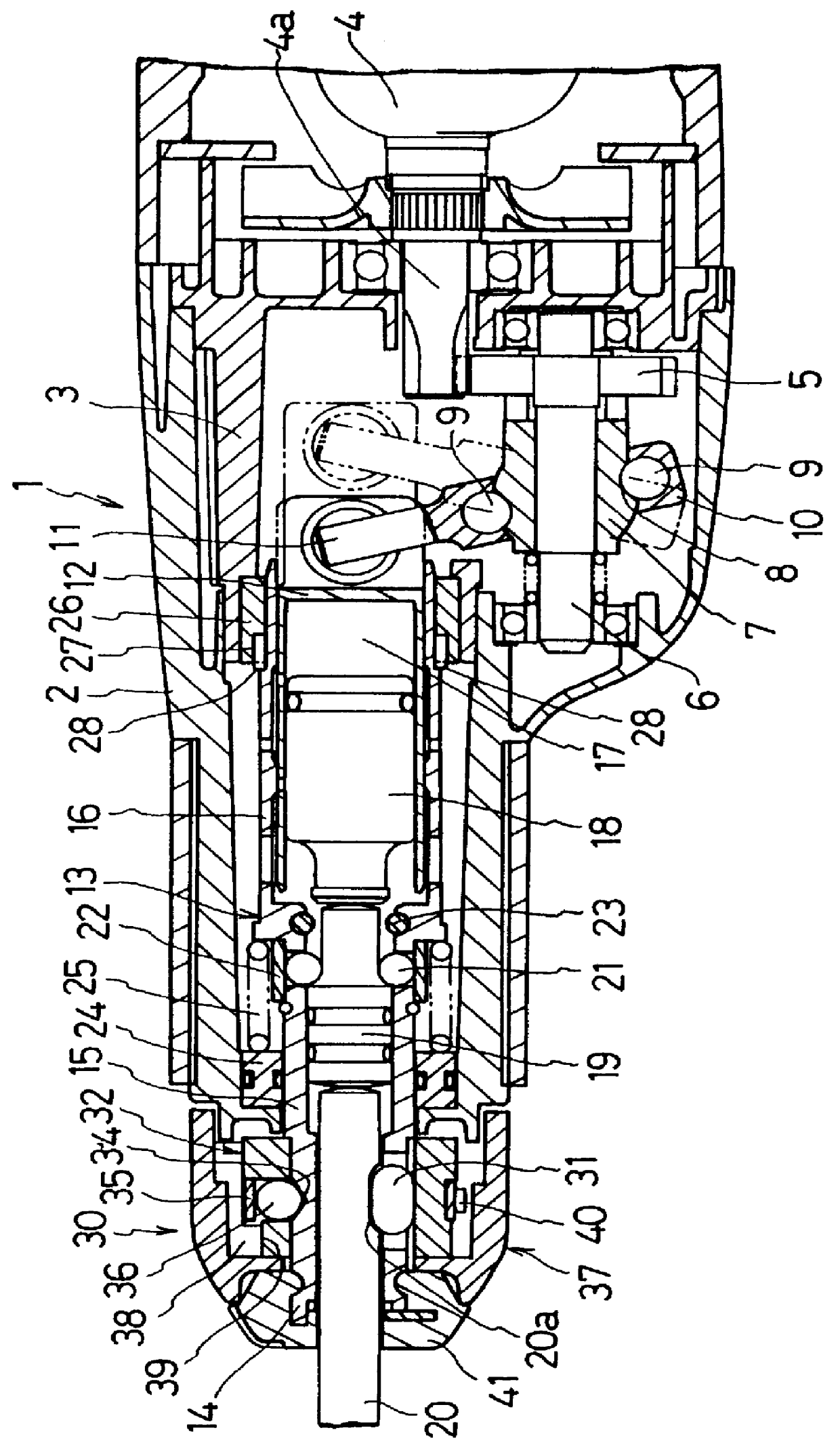
FIG. 1 depicts a vertical sectional view of a power-driven hammer 1 constructed according to the present invention. A motor 4 is disposed in the rear of the hammer 1, which is to the right of the figure, with its shaft 4a meshed with a helical gear 5. A gear shaft 6 is formed through, and integrally with, the helical gear 5 and supported in parallel to the motor shaft 4a. The rotation of the motor 4 is thus transmitted via the shaft 4a and the helical gear 5 to the gear shaft 6. A boss 7 is fitted around and rotatable integrally with the gear shaft 6. An annular groove 8 is formed in the boss 7 at an angle to the axis of the gear shaft 6. A ring 10 is loosely fitted on the boss 7 with a plurality of balls 9 received in the annular groove 8. An arm 11 extending from the ring 10 is connected with the rear end of a piston cylinder 12. When the gear shaft 6 and the boss 7 are rotated together, the annular groove 8 and the balls 9 cooperatively cause the ring 10 to move back and forth, t...


PUM

PropertyMeasurementUnit
Angleaaaaaaaaaa

Abstract

A power-driven hammer has a tool holder a middle bore portion which is supported inside a housing and urged backward by a compression spring. The rear end of a large bore portion of the tool holder is slidably fitted into a spline ring which is secured to the front end of a middle housing. Spline grooves are formed in the inner periphery of the spline ring at its front end while spline gears are formed on the outer periphery of the large bore portion. When the spline grooves and the spline gears are engaged with each other, the tool holder, being urged backward, is locked with its rotation prohibited. This tool holder can be temporarily unlocked to allow its rotation by sliding a change ring cover forward and the tool holder itself, thereby disengaging the large bore portion from the spline ring.

Description

1. Field of the inventionThis invention relates to a power-driven tool in which a tool bit is mounted in the front end of the tool holder which is rotatably supported in the hammer body. More specifically, this invention relates to such a power-driven tool in which the rotary angle position of a tool bit is adjustable after the tool bit is attached.2. Description of the Prior ArtGenerally, a tool bit attached to the power-driven tool is integrally rotatable with the tool holder by means of a lock mechanism provided in the front of a power-driven tool. Some tool bits, such as chisels, need to be fixed in the tool holder at an appropriate rotary angle position for ease of use. Japanese Patent Application Laying-Open Gazettes Nos. 54-27801 and 61-19395, address such a need. In these prior-art hammer drills, a tool bit is engaged with or disengaged from a clutch member disposed between the tool holder and the output gears for selecting an operation mode from: a drill mode in which only ...

Claims


Application Information

Patent Timeline
IPC IPC(8): B25D17/08B25D17/00B23Q3/12B23B45/16B25D11/04B25F5/00
CPCB25D17/088B25D2217/0049B25D2217/0042
Inventor SHIBATA, MITSUYOSHIUCHIDA, MASAAKI
Owner MAKITA CORP
Why Eureka
Try Eureka