Accumulator pressure control in vehicle brake systems

a technology of accumulation pressure control and vehicle brake system, which is applied in the direction of braking system, vehicle components, transportation and packaging, etc., can solve the problems of high cost of suitable transducers or switches with appropriate accuracy, and add significantly to the cost of such braking systems

Inactive Publication Date: 2000-10-17
LUCAS IND PLC
View PDF6 Cites 36 Cited by
  • Summary
  • Abstract
  • Description
  • Claims
  • Application Information

AI Technical Summary

Problems solved by technology

However, the use of such pressure transducers or pressure switches adds significantly to the cost of such braking systems, particularly where the window or pressure range over which the pressure is being controlled is small, since the cost of suitable transducers or switches with appropri

Method used


Image

  • Accumulator pressure control in vehicle brake systems
  • Accumulator pressure control in vehicle brake systems
  • Accumulator pressure control in vehicle brake systems

Examples


Embodiment Construction

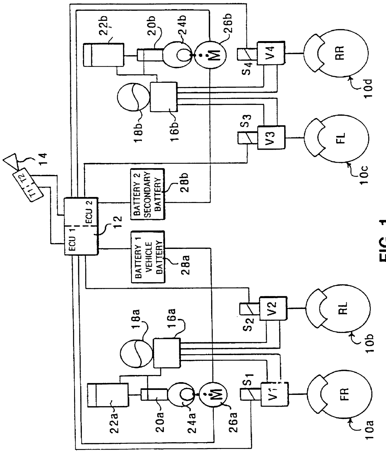
Referring first to FIG. 1, the illustrated braking system comprises a plurality of wheel brakes 10a, 10b, 10c, 10d bearing the designations FR (front right), RL (rear left), FL (front left) and RR (rear right). These brakes are driven by way of respective proportional pressure control valves V1, V2, V3 and V4 controlled by solenoids S.sub.1, S.sub.2, S.sub.3 and S.sub.4 energised by primary (ECU1) and secondary (ECU2) sections of an electronic control unit 12. The electronic control unit 12 receives driver demand input signals corresponding to driver braking demand from transducers T1, T2 responsive to displacement of a driver controlled input pedal 14.

In this example, the front brake FR and rear brake RL are supplied with actuating fluid from a hydraulic unit 16a coupled to a first accumulator 18a and the front brake FL and rear brake RR are supplied with actuating fluid from a hydraulic unit 16a coupled to a second accumulator 18b. The accumulators 18a, 18b are themselves coupled ...


PUM


Abstract

PCT No. PCT/GB96/01731 Sec. 371 Date Apr. 17, 1998 Sec. 102(e) Date Apr. 17, 1998 PCT Filed Jul. 18, 1996 PCT Pub. No. WO97/05001 PCT Pub. Date Feb. 13, 1997A vehicle braking system in which a stored volume of working fluid is used by a brake control system to apply the brakes under the control of an electronic control unit. The stored volume is replenished by pumping additional working fluid using a pump driven by an electric motor. The electric motor is periodically energized. An inferred value is established for the accumulator pressure based on an assessment of the motor response during the periods of energization. The electric motor can be arranged to be energized for short periods at predetermined intervals and the motor response during these periods assessed. From this assessment, either the switch-on point for driving the pump motor for the purpose of recharging the stored volume of working fluid is determined from the level of motor torque applied during the short periods of energization, or, where the system includes a pressure sensor for detecting the working fluid pressure, a signal for corroborating the signal of the pressure sensor is established from the level of motor torque applied during the short periods of energization.

Description

1. Field of the InventionThe present invention relates to vehicle braking systems and is concerned in particular with an apparatus and method for assessing and controlling the pressure level within an accumulator from a pumped supply in such braking systems.The present apparatus and method can be applied, inter alia, not only to pneumatic braking systems where a compressor charges air tanks of the braking system but also, as in the examples described hereinafter, to systems wherein a fluid pump is arranged to charge a high-pressure fluid accumulator. In both of these cases, the stored volume of working fluid is used by a brake control system to apply the brakes of the vehicle, under the control of an electronic control unit.The brake control system is required to ensure that a volume of working fluid is available for operating the brakes and which remains within a prescribed pressure window, ie. between upper and lower thresholds of pressure. When the system is operated, the stored ...

Claims


Application Information

Patent Timeline
IPC IPC(8): B60T17/02B60T13/14B60T13/10B60T17/00B60T8/40B60T13/66
CPCB60T8/4045B60T17/02B60T13/148B60T8/4054
Inventor HOLT, MICHAEL JOHNBRIDGENS, BARRY JOHN
Owner LUCAS IND PLC
Why Eureka
Try Eureka