Variable length truss and method for producing the same

a technology of variable length and trusses, which is applied in the direction of girders, joists, chemistry apparatus and processes, etc., can solve the problems of requiring old growth timber, reducing the strength of the strut, so as to achieve greater on-center spacing and increase the strength. , the effect of saving

Inactive Publication Date: 2000-10-31
TRIMJOIST
View PDF30 Cites 12 Cited by
  • Summary
  • Abstract
  • Description
  • Claims
  • Application Information

AI Technical Summary

Benefits of technology

Modern, high strength, structural adhesives and special equipment make possible the fabrication of end sections without the use of any mechanical fasteners so that lengths may be modified in the field.
B. Higher strength allows longer spans with greater on-center spacing-resulting in a net savings in total board-feet of wood fiber (about 12% less than typical 2.times.12 construction) and less deflection.
C. Open web construction allows for easy passage of duct work, conduit and pipe throughout the length of the TrimJoist-no more hole cutting or notching with consequent problems.
D. The 4.times.2 chord orientation provides a greater nailing surface for decking, thereby reducing squeaks and giving a more rigid floor system. Minimum chord grade is #1 SP in the preferred embodiment.

Problems solved by technology

The major problems associated with these are that they require old growth timber to provide wide enough lumber.
In addition, when oriented edgewise, they provide an inferior nailing surface compared with that provided by two by fours oriented flatwise.
The net effect of trimming a truss of this form would be to affect the structural integrity built into the truss by virtue of the fillets and cause potential splitting at the channels holding the struts.
One of the problems recognized by the present example is that I-beam construction of this type results in an inability to make on site corrections to the length of trusses.
This problem can result in the need to re-manufacture the entire truss.
As with Keller, this creates a number of problems.
First, at least a portion of the interior webbing is closed and cannot be used for running lines or conduit without bracing, known generally in the art as web stiffeners, being added and calculations being necessary for determining the stability and crush strength of the altered bracing.
Closed truss design suffers from several construction problems.
First, the design requires a great deal more material, having a closed volume.
Second the design has difficulty with respect to working within the area defined by the interior of the truss since it is solid and must be cut for additional work.
This provides for two problems.
First, the strength of the truss may be affected by the work.
Second, a great deal of time and equipment may be necessary in order to manufacture a space in which to work.
Other related problems may exist as a result of these general problems including the need to use "web stiffeners" and engineer where holes may be made and where web stiffeners are to be placed.
In addition to other reasons, the weight of these types of trusses make them hard to ship and hard to work with.
The major problems with the solid web, other than the inability to use it easily in the field without engineering to pass conduit, is the cost.
Solid webbing of the type needed to distribute stress is an expensive value added wood manufactured product comprises of glue and chips compressed together.
The prior art has failed to date to provide an open web truss which has a variable length and this failing has required that all cross web construction be made to order requiring huge risks of error, high turn around times and inflexibility for the end user.
The prior art also fails to show a trimmable truss which does not require on site modification to maintain crush strength.
The prior art also fails to show a method for constructing trusses with web strengtheners in place at a low cost.

Method used


Image

  • Variable length truss and method for producing the same
  • Variable length truss and method for producing the same
  • Variable length truss and method for producing the same

Examples


Embodiment Construction

)

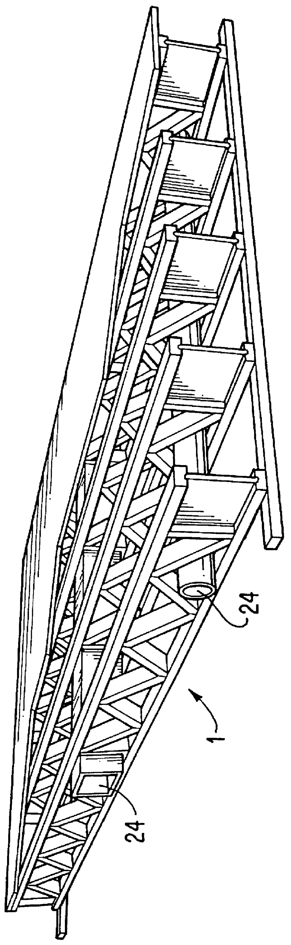
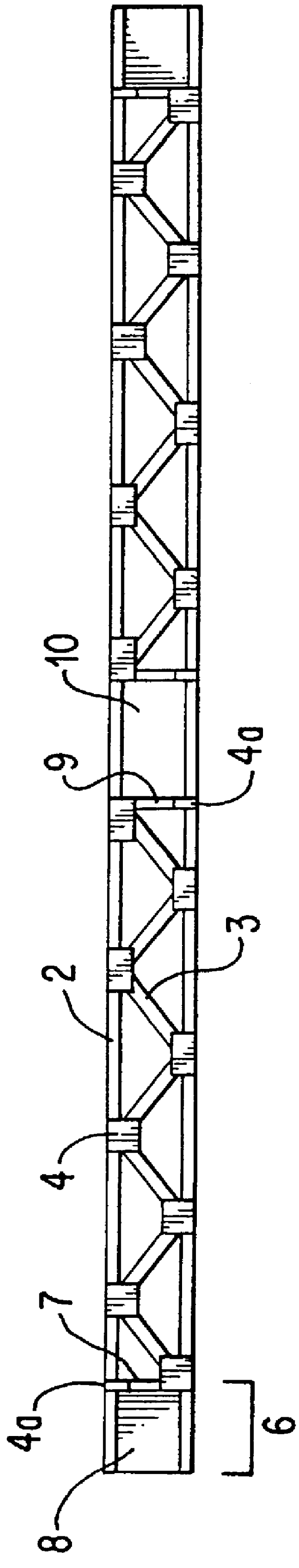
As can best be seen by reference to FIG. 1, the structural component system 1 is constructed of a series of individual truss members as shown as 2 in FIG. 2 and the ends of the structural component are constructed of wooden flanges separated by a vertical wooden solid web material.

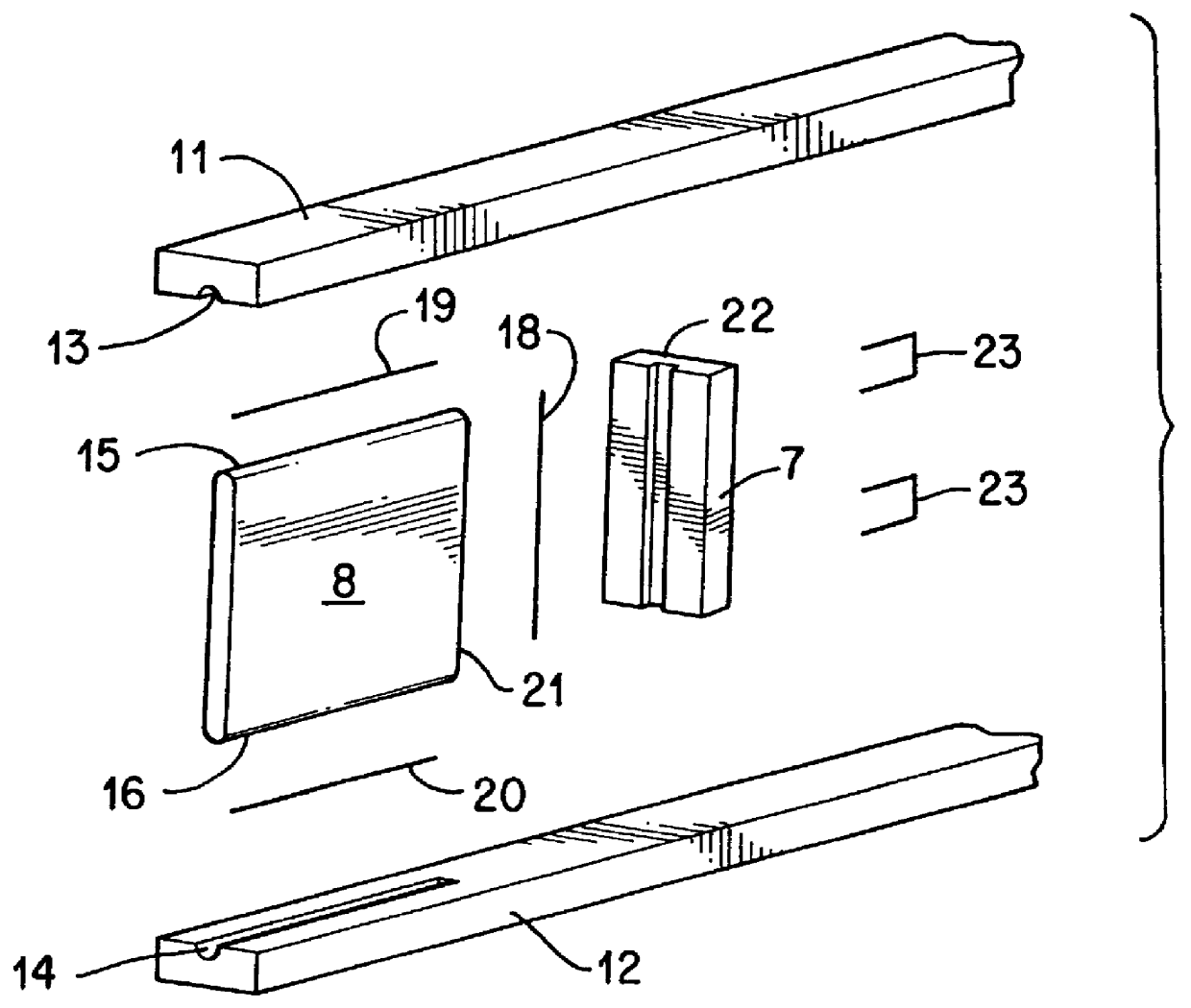
As can best be seen by FIG. 2, each of the cross member 3 is constructed generally using cross beams 3 and chords 5. An end unit 6 comprised of a strut 7 and a closed or solid web 8 complete the interior portions. The chords are bound to the struts 7 and the cross members 3 utilizing metal fasteners 4. These fastener 4 are known in the art and appear as a metal sheet out of which sharp points or nails have been punched. Typically, these fasteners 4 need to be in place on both sides of the cross beams 3, struts 7 and chords 11 and 12. A smaller fastener 4a is used in order to secure the top or bottom of vertical beams 9 defining duct opening 10 and the top of struts 7.

The strut may be slanted as required b...


PUM

PropertyMeasurementUnit
lengthaaaaaaaaaa
lengthaaaaaaaaaa
sizeaaaaaaaaaa

Abstract

An open web beam composed of wooden top chord and an open web central structure terminated on at least one end by wooden members in the form of a closed web wherein the closed web is reinforced by insertion of a portion of the closed web into a strut and the two chords which have been slotted or grooved for this purpose. The closed be being oriented strand board using structural adhesive without interfering mechanical fasteners in the web.

Description

This invention relates broadly to the art of construction trusses and joists.More particularly the invention relates to open web truss designs for application to ceiling, roof and floor joists.More particularly the invention relates to a process and product for use as trimmable trusses or joist which combine the benefits of open web truss construction with closed web construction providing variable length while conserving the integrity of the factory test requirements and component strength with variable spans.Truss designs in the prior art envision three broad design types.Two by ten or two by twelve joists made of solid wood are very common. The major problems associated with these are that they require old growth timber to provide wide enough lumber. In addition, when oriented edgewise, they provide an inferior nailing surface compared with that provided by two by fours oriented flatwise. This is particularly important when adding subfloors and ceilings to the joists since only a...

Claims


Application Information

Patent Timeline
Patent Type & Authority Patents(United States)
IPC IPC(8): E04C3/12E04C3/16
CPCE04C3/16Y10T156/1074Y10T156/1066Y10T156/108Y10T156/1064
Inventor SANFORD, EMMETT BARRYSANFORD, JR., EMMETT CECIL
Owner TRIMJOIST
Why Eureka
Try Eureka