Housing for a multiplate clutch

Inactive Publication Date: 2000-11-07
SACHS RACE ENG
View PDF27 Cites 16 Cited by
  • Summary
  • Abstract
  • Description
  • Claims
  • Application Information

AI Technical Summary

Benefits of technology

Using a construction of this type, it is possible to dispense completely with the provision of any bolts for connecting the individual housing components. This reduces the mass and thus the moment of inertia of the housing considerably according to the invention, and also contributes to a distinct reduction in manufacturing costs, since the bolts used in the prior art for holding the housing together were generally designed as reduced-shank bolts, and had to be produced with high precision and were thus expensive.
In particular when connecting the toothed ring and the flywheel disk or, respectively, the cover by welding, it is advantageous if the welded connection between the toothed ring and the flywheel disk or, respectively, the cover is interrupted in the area of the securing cutout, and a relief hole cutting into the welded connection is provided at least one end of the welded connection. It is thus possible to avoid notch stresses being produced during operation in this end region of a welded seam.

Problems solved by technology

However, this requirement runs contrary to holding the components forming the housing together by means of a plurality of bolts, since, on the one hand, in order to provide the desired stable holding together, these bolts have to be constructed very solidly and, on the other hand, are positioned in radially outer regions of the housing, so that they significantly contribute to the moment of inertia of such clutches.

Method used


Image

  • Housing for a multiplate clutch
  • Housing for a multiplate clutch
  • Housing for a multiplate clutch

Examples


Embodiment Construction

Before the details of the present invention are discussed, the construction of a multiplate clutch will be described in general terms with reference to FIG. 9.

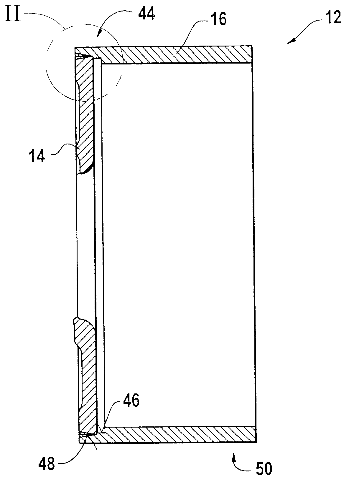
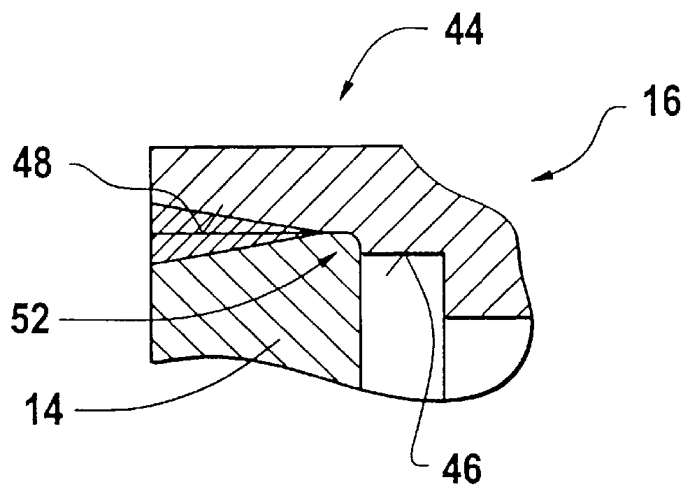
A multiplate clutch 10 comprises a housing, designated generally by 12, formed of a flywheel disk 14, a toothed ring 16 and a cover 18. The flywheel disk 14 can be screwed onto a drive shaft, for example a crankshaft of an internal combustion engine, by means of a plurality of bolts 20, so that the housing 12 will rotate about an axis of rotation A, driven by this drive shaft, after it has been integrated into the drive system.

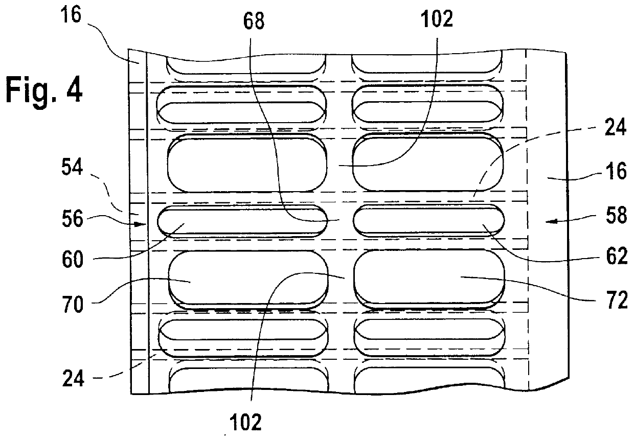
The toothed ring 16 has a plurality of multiplate driver teeth 24 which are arranged on an inner peripheral surface 22 of said ring, distributed in the peripheral direction, and extend in a ring longitudinal direction which corresponds to the direction in which the axis A extends. Respective outer teeth 26 of outer plates 28, of which four can be seen in FIG. 9, engage in the multiplate driver teeth 24. ...


PUM

PropertyMeasurementUnit
areaaaaaaaaaaa
shapeaaaaaaaaaa
magneticaaaaaaaaaa

Abstract

A housing for a multiplate clutch includes a toothed ring having a plurality of multiplate driver teeth arranged on an inner peripheral surface thereof distributed in the peripheral direction, and extending in a ring longitudinal direction. A flywheel disk is connected to the toothed ring at a first end of the same for common rotation. A cover is connected to the toothed ring at a second end of the same for common rotation. In this case, the toothed ring is connected to the flywheel disk by welding.

Description

1. Field of the InventionThe present invention relates to a clutch housing for a motor vehicle and more particularly, it relates to a housing for a multiplate clutch.2. Description of the Related ArtA multiplate clutch housing is disclosed, for example, by DE 195 45 972 A1. In a known multiplate clutch of this type, the housing, that is to say the flywheel disk, the toothed ring and the cover, are held together by bolts which pass axially through these three components. The bolts are respectively guided in openings which pass through the multiplate driver teeth and corresponding openings in the flywheel disk and the cover.Multiplate clutches of this type are generally used in the motorsport sector, and it is an objective to design these clutches to have the lowest possible weight and the lowest possible moment of inertia. However, this requirement runs contrary to holding the components forming the housing together by means of a plurality of bolts, since, on the one hand, in order t...

Claims


Application Information

Patent Timeline
Patent Type & Authority Patents(United States)
IPC IPC(8): F16D13/52F16D13/00F16D13/58F16D13/60
CPCF16D13/52B60Y2200/114Y10T29/4978
Inventor PINSCHMIDT, UDORUDOLF, THOMASSELZAM, WERNERFRIEDRICH, HORSTORTH, CLAUSHOFMANN, KLAUS
Owner SACHS RACE ENG
Why Eureka
Try Eureka