Hydraulic circuit having a rotary type pump and brake apparatus for a vehicle provided with the same

a technology of hydraulic circuit and brake apparatus, which is applied in the direction of braking system, braking components, transportation and packaging, etc., can solve the problems of high brake fluid pressure in the auxiliary conduit, inability to ensure the braking force of the rear-right and rear-left wheels, and easy slippage of the rear wheels

Inactive Publication Date: 2000-11-07
DENSO CORP
View PDF49 Cites 77 Cited by
  • Summary
  • Abstract
  • Description
  • Claims
  • Application Information

AI Technical Summary

Problems solved by technology

Further, the brake fluid pressure in the auxiliary conduit becomes high due to brake fluid pressure produced by a braking operation of a driver.
There may be cases wherein assurance of braking force in the rear-right and rear-left wheels cannot be expected due to load movement occurring during vehicle braking.
When great load movement occurs, it even arises possibility that the rear wheels become prone to slippage when large braking force is applied to the rear wheels.
Furthermore, because this structure making it difficult for the brake-fluid pressure to reach the conduit's breakdown pressure does not utilize any sensors or the like, but rather utilizes the circuit structure itself, safety thereof is extremely high and is unaffected by failure of sensors or the like.
That is to say, in a case where antiskid control cannot favorably be performed, increase of the wheel-cylinder pressure by the pump 15 of the pressure-amplifying device 10 is caused to be impossible.
Therefore, even in a case where the pump 15 fails and antiskid control becomes impossible, increase in the wheel-cylinder pressure by the pressure-amplifying device 10 naturally also becomes impossible.
Consequently, in a case where, for example, a state in which power braking cannot be normally used has occurred due to an abnormality in the pump 15, the brake-fluid pressures of the front-wheel side and the rear-wheel side may become equal, and the rear-wheel side may become susceptible to locking prior than the front-wheel side.
As a result, braking may become unstable.

Method used


Image

  • Hydraulic circuit having a rotary type pump and brake apparatus for a vehicle provided with the same
  • Hydraulic circuit having a rotary type pump and brake apparatus for a vehicle provided with the same
  • Hydraulic circuit having a rotary type pump and brake apparatus for a vehicle provided with the same

Examples


first embodiment

A twenty-first embodiment will be described next.

According to this embodiment in particular, a G sensor is utilized to detect deceleration of the vehicle body, and a starting reference value for execution ("on") or stopping ("off") of power assist is varied in accordance with output therefrom.

As indicated in the flowchart in FIG. 45, according to this embodiment, firstly, in step S70, it is determined whether a brake switch 113 is on. When the determination herein is affirmative, the processing advances to step S71; when the determination is negative, the processing is terminated.

In step S71, body deceleration Y is detected on a basis of a signal from the G sensor.

Next, in step S72, starting reference value (operation change-quantity threshold value) dXs for starting brake assist is varied in accordance with the body deceleration.

In step S73, operated quantity X of the brake pedal 1 is detected, and in the subsequent step S74, the operated quantity X of the brake pedal 1 is differen...

second embodiment

A twenty-second embodiment will be described next with reference to the flowchart in FIG. 46.

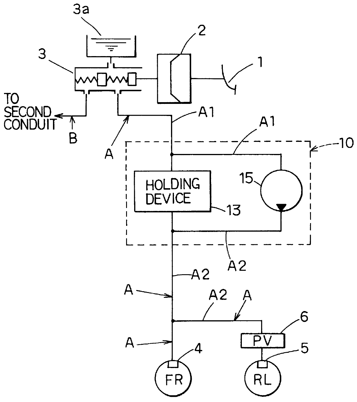
Devices described in the embodiments hereinabove can be employed for the structure of the brake apparatus or the structure of the ECU. Additionally, a booster 2 is utilized as a first amplifying device, and a pressure-amplifying device 10 is employed as a second amplifying device.

The flowchart indicated in FIG. 46 is executed by an electronic control unit 12 in accompaniment to operation to switch on an ignition switch or the like by a driver. In step S80, wheel speed VW of several wheels is calculated on a basis of output from wheel-speed sensor (not illustrated). Next, in step S81, wheel deceleration dVW is calculated on a basis of the wheel speed VW.

In step S82, it is determined whether a brake switch 113 is in an "on" state, i.e., whether a brake pedal 1 has been depressed by a predetermined amount or more and the vehicle is in a braking state. The processing advances to step S83 in a ca...

third embodiment

A twenty-third embodiment will be described next with reference to FIG. 48 and FIG. 49.

In control according to the embodiment described hereinabove, the second amplifying device was executed on a basis of wheel deceleration dVW corresponding to wheel behavior depending on a road-surface state. According to the twenty-third embodiment, however, the second amplifying device, i.e., a pressure-amplifying device 10, is executed on a basis of pedal stroke PS of a brake pedal 1 when operated by a driver.

In flowchart started in accompaniment to operation of an ignition switch to an "on" position or the like, as shown in FIG. 48, in step S90, pedal stroke PS is detected on a basis of a signal from a stroke sensor 111. Next, in step S91, this pedal stroke PS and a predetermined value KPS are compared. This predetermined value KPS may be established in light of pedal stoke, for example, when the driver depresses the brake pedal 1 to stop the vehicle suddenly during vehicle travel at a body spe...


PUM


Abstract

A hydraulic circuit has a rotary type pump comprising a rotor rotating with a driving shaft and a casing which holds the rotor and the driving shaft. The casing further comprises an inlet port through which fluid is introduced to spaces formed by the rotor, an outlet port through which fluid is discharged from the spaces, and a hydraulic path for leading fluid from clearance around said driving shaft to the outside of the casing. A reservoir is provided to store fluid coming through the hydraulic path. A return conduit is disposed between the reservoir and an upstream side conduit connected to the inlet port in order that fluid stored in the reservoir is returned to the upstream side conduit. In the return conduit, a check valve is disposed to prevent the reverse flow of fluid from the upstream side conduit to the reservoir.

Description

1. Field of the InventionThe present invention relates to a hydraulic circuit having a rotary type pump and a brake apparatus provided with the hydraulic circuit having the rotary type pump.2. Related ArtsA schematic view of a conventional inner-contact rotary type pump is shown in FIG. 67A. A sectional view taken on line 67B--67B in FIG. 67A is shown in FIG. 67B. As shown in FIG. 67A, an outer rotor 351 and an inner rotor 352 are assembled in a rotor chamber of a casing 350 of the inner-contact rotary type pump. An inner teeth portion 351a is formed on an inner periphery of the outer rotor 351 and an outer teeth portion 352a is formed on an outer periphery of the inner rotor 352. The inner teeth portion 351a and the outer teeth portion 352a are engaged to each other while forming a gap 353 therebetween. As shown in FIG. 67B, a center hole 350a is formed at a center of the casing 350 and a driving shaft 354 to be connected to the inner rotor 352 is inserted into the center hole 350a...

Claims


Application Information

Patent Timeline
Patent Type & Authority Patents(United States)
IPC IPC(8): B60T8/40B60T7/12B60T13/68B60T8/32B60T17/02B60T8/26B60T13/10B60T13/16B60T17/00B60T8/44B60T8/24B60T8/34B60T8/48B60T8/42
CPCB60T7/12B60T8/26B60T8/3275B60T8/348B60T8/4018B60T8/4031B60T8/4036B60T8/4045B60T8/4095B60T8/4275B60T8/441B60T8/4872B60T13/161B60T13/686B60T17/02B60T7/122B60T2201/03
Inventor YAMAGUCHI, TAKAHIROMORIKAWA, TOSHIYAYONEMURA, SHUICHIABE, YOICHISAWADA, MAMORU
Owner DENSO CORP
Why Eureka
Try Eureka