Collapsible spline structure using a balloon as an expanding actuator

a balloon and actuator technology, applied in the field of medical catheter devices, can solve the problems of unproven chemical ablation technology, large electrodes, and high cost, and achieve the effects of large electrodes, reliable consistent results, and large lesions

Inactive Publication Date: 2000-11-07
EP TECH
View PDF6 Cites 803 Cited by
  • Summary
  • Abstract
  • Description
  • Claims
  • Application Information

AI Technical Summary

Benefits of technology

It is an advantage of the present invention that relatively large lesions can be produced in the body generally wherever such lesions are desired and where a catheter can be introduced thereto.
It is yet another advantage of the present invention that a relatively large electrode can be collapsed both for introduction and removal through a catheter.
It is still another advantage of the invention that reliably consistent results can be obtained in the production of

Problems solved by technology

However such methods are expensive and technically difficult and are, therefore, only rarely attempted.
It is known that an 8 French ablation tip generally does not create large enough lesions to ablate VT substrates, especially those positioned intramural or on the epicardial surface.
Other technologies including microwave, laser, ultrasound, and chemical ablation are unproven and will require an extensive development process.
Fluid cooling technology using RF power and currently available tip sizes increases lesion size by forcing the maximal temperature deeper into the tissue, but this may be accompanied by complications due to "popping"

Method used


Image

  • Collapsible spline structure using a balloon as an expanding actuator
  • Collapsible spline structure using a balloon as an expanding actuator
  • Collapsible spline structure using a balloon as an expanding actuator

Examples


embodiment 22

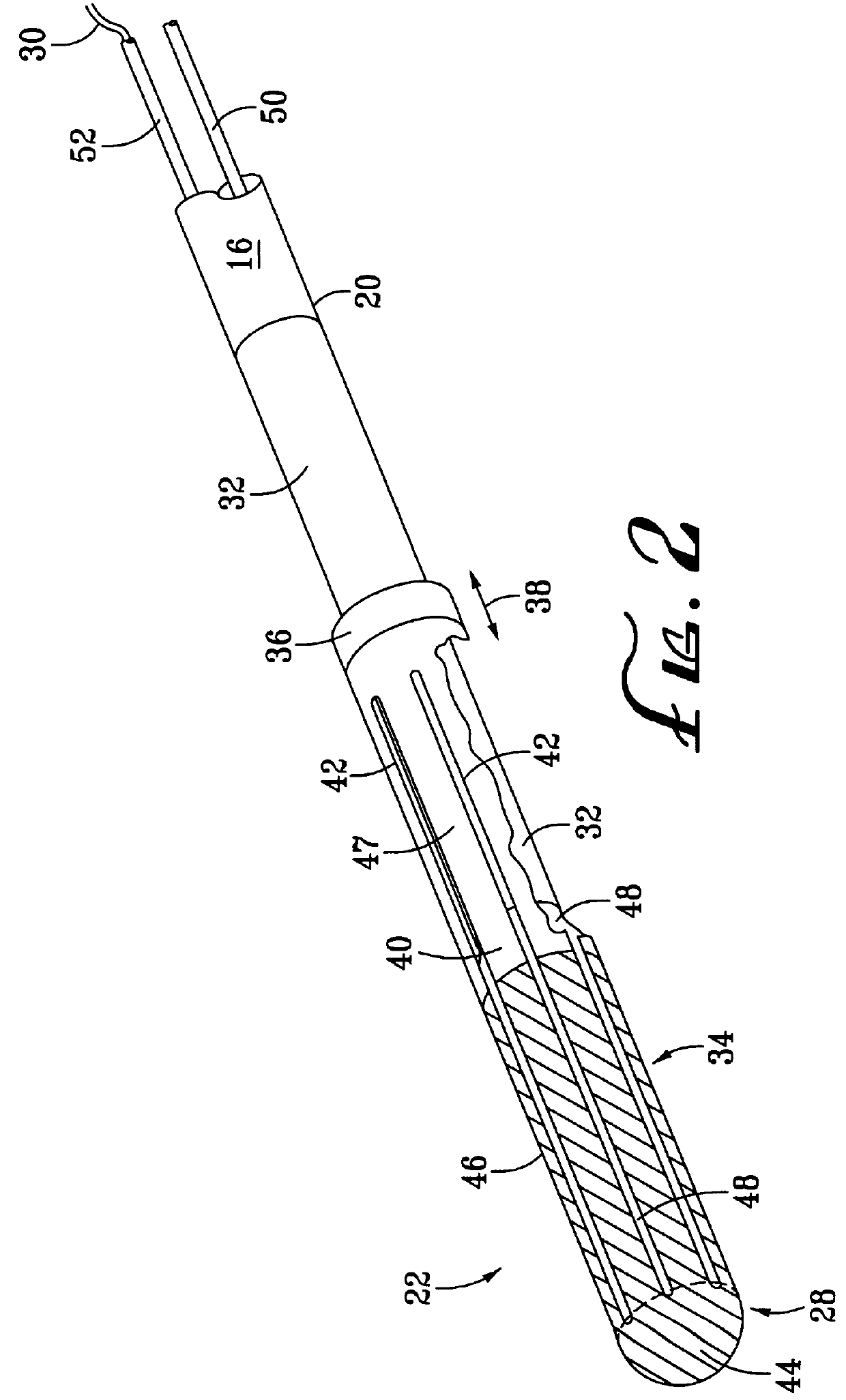
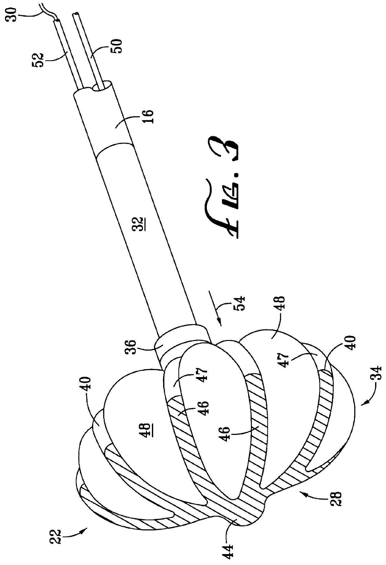
A plurality of splines 40 are created in the expanding assembly 34 by the removal of material from the expanding assembly 34 to create a plurality of slots 42 therein. In the example of FIG. 2 there are eight splines 40 (four of which are visible in the view of FIG. 2) and eight slots 42 (three of which are visible in the view of FIG. 2), although these quantities are subject to variance, as will be discussed in greater detail hereinafter. A cap portion 44 is located at the distal end of the expanding assembly 34 for joining the splines 40 at that end. As can be seen in the view of FIG. 2, the cap portion is rounded such that the catheter distal end assembly 22 can readily be introduced intravascularly without unnecessarily damaging vascular tissue. The electrode structure 28 can be seen to cover the cap portion 44 of the expanding assembly 34 and a conductive portion 46 of the splines 40. A non-conductive substrate 47 of the splines 40 can be seen in the view of FIG. 2 where the el...

embodiment 10

FIG. 4 is an end view of the catheter distal end assembly 22 in the expanded condition as depicted also in the view of FIG. 3. In the view of FIG. 4, only a part of the conductive portion 46 of the splines 40 is visible, the nonconductive portion 47 thereof being obscured behind the curve of the balloon structure 48 in this view. An imaginary circle indicated by a dotted line in the view of FIG. 4 describes an intended contact area 56 of the electrode structure 28, which is that portion of the electrode structure 28 and adjacent portions of the balloon structure 48 which are expected to come into effective contact with tissue to be ablated. While it is anticipated that there may be numerous dimensional aspects and variations in the shape of the electrode structure 28 as might be appropriate to different applications, the inventors have determined that a size 8F catheter distal end assembly 22 according to the best presently known embodiment 10 of the present invention will have eigh...

embodiment 70

FIG. 6 is a perspective view of an equally preferred alternate embodiment 70 of the present invention, shown in the expanded condition. It should be noted that the first preferred catheter distal end assembly 22 of this invention, as discussed previously herein, has but the single electrode structure 28, thus constituting a unipolar device. One skilled in the art will recognize that this arrangement will generally require the use of a second electrode located either inside or outside the body, and such devices and related procedures are known in the art. Alternatively, however, the equally preferred alternate embodiment 70 illustrated in FIG. 6, while otherwise similar in construction to the embodiments described in relation to FIGS. 2 through 5, has a plurality of individual electrodes 72 separately dispersed along the splines 40 of the alternate catheter distal end assembly 70. The individual electrodes 72 allow the connection, for example of a first wire 74a to a first individual...


PUM

PropertyMeasurementUnit
Poweraaaaaaaaaa
Temperatureaaaaaaaaaa
Structureaaaaaaaaaa

Abstract

A collapsible electrode catheter assembly (10) having a delivery system (12) for controlling a catheter guide tube (16) having a catheter distal end assembly (22) thereon. The catheter distal end assembly (22) has an electrode structure (28) on an expanding assembly (34) for enlarging the electrode structure (28) in an expanded condition. A balloon structure (48) is used to expand and contract the expanding assembly (34) when an inflation medium (64) is alternately introduced into and withdrawn from the balloon structure (48).

Description

1. Field of the InventionThe present invention relates generally to medical catheter devices, and more particularly to tissue ablation catheters having expandable distal end assemblies. The predominant current usage of the inventive ablation catheter with collapsible electrode is in the field of medical catheter surgery in applications wherein it is desirable to produce a lesion of substantial size.2. Description of the Prior ArtIt is known in the medical field that an important method for correcting cardiac fibrillation is to interrupt unwanted potential electrically conductive pathways or "reentry circuits" whereby electrical impulses are misdirected in the heart. This has been done surgically using open heart surgery methods. However such methods are expensive and technically difficult and are, therefore, only rarely attempted. An alternative, and generally superior method has been to accomplish the same result using electrical ablation with the electrodes being introduced into t...

Claims


Application Information

Patent Timeline
IPC IPC(8): A61B18/14
CPCA61B18/1492A61B2018/1497A61B2018/00148A61B2018/0016A61B2018/00196A61B2018/00214A61B2018/00232A61B2018/00351A61B2018/00577A61B2018/00654A61B2018/00702A61B2018/00714A61B2018/0075A61B2018/00791A61B2018/00797A61B2018/1253A61B2018/126A61B2017/003
Inventor WHAYNE, JAMESYANG, YI
Owner EP TECH
Why Eureka
Try Eureka