Press form element, method of installation and assembly

a form element and press technology, applied in the direction of screws, nuts, bolts, etc., can solve the problems of not being able to achieve liquid-tight and/or gas-tight mounting, and not being able to produce a connection between functional elements in a straightforward manner, and achieve the effect of little hea

Inactive Publication Date: 2000-11-14
HVB BANQUE LUXEMBOURG
View PDF37 Cites 30 Cited by
  • Summary
  • Abstract
  • Description
  • Claims
  • Application Information

AI Technical Summary

Benefits of technology

The object of the invention is to make available a method and / or a functional element and a component assembly in which a connection which is at least substantially always liquid-tight and preferably also gas-tight is ensured between the functional element and the sheet metal part with a procedure which involves little heat and indeed without any eventually present coating of the sheet metal part being so damaged that the functionality of the desired appearance of the component assembly is no longer present. Furthermore, the method should be capable of being achieved without special complexity during the mass manufacture of sheet metal parts using favorably priced tools and over long production series.
Since the sheet metal part is not perforated during the attachment of the functional element, the sheet metal part is so to say preserved as a closed membrane so that no capillary gaps can arise between the two sides of the sheet metal part. It is admittedly not straightforwardly possible in this manner to produce a connection between the functional element and the sheet metal part which has the same resistance to pulling out of the functional element as a connection in which the head part of the element is arranged on the other side of the sheet metal from the shaft part. One can, however, certainly achieve an adequate strength of the connection, which is fully sufficient in many of the applications which exist and in which the maximum strength of the connection is not required, for example for the attachment of carpets in vehicles for the mounting of headlinings in vehicles or during installation of brake lines, cables, lamps and the like.
For this reason it is frequently possible to eliminate, in cost saving manner, features in the die button which would lead to a closed hooked engagement with the features of the functional element providing security against rotation. For example, when using features providing security against rotation in accordance with the above mentioned copending U.S. patent application, the corresponding noses at the die button could be omitted. Through the multi-cornered shape of the sheet material which is deformed into the hollow cavity of the element, an adequate security against rotation is achieved with the subject of the present application without the use of these noses. This also has the advantage that the coated surface of the sheet metal part is also not damaged by tile noses.

Problems solved by technology

It is admittedly not straightforwardly possible in this manner to produce a connection between the functional element and the sheet metal part which has the same resistance to pulling out of the functional element as a connection in which the head part of the element is arranged on the other side of the sheet metal from the shaft part.
With these punch rivets a perforation of the sheet metal part via the punch rivet is not necessarily intended, but however occurs in some cases when considered statistically, so that this known method also does not make it possible to achieve a liquid-tight and / or gas-tight mounting, which is suitable for mass production.

Method used


Image

  • Press form element, method of installation and assembly
  • Press form element, method of installation and assembly
  • Press form element, method of installation and assembly

Examples


Embodiment Construction

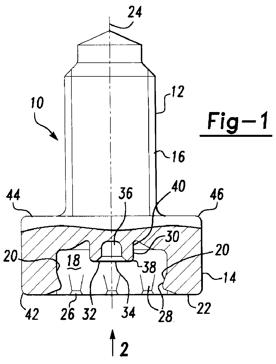
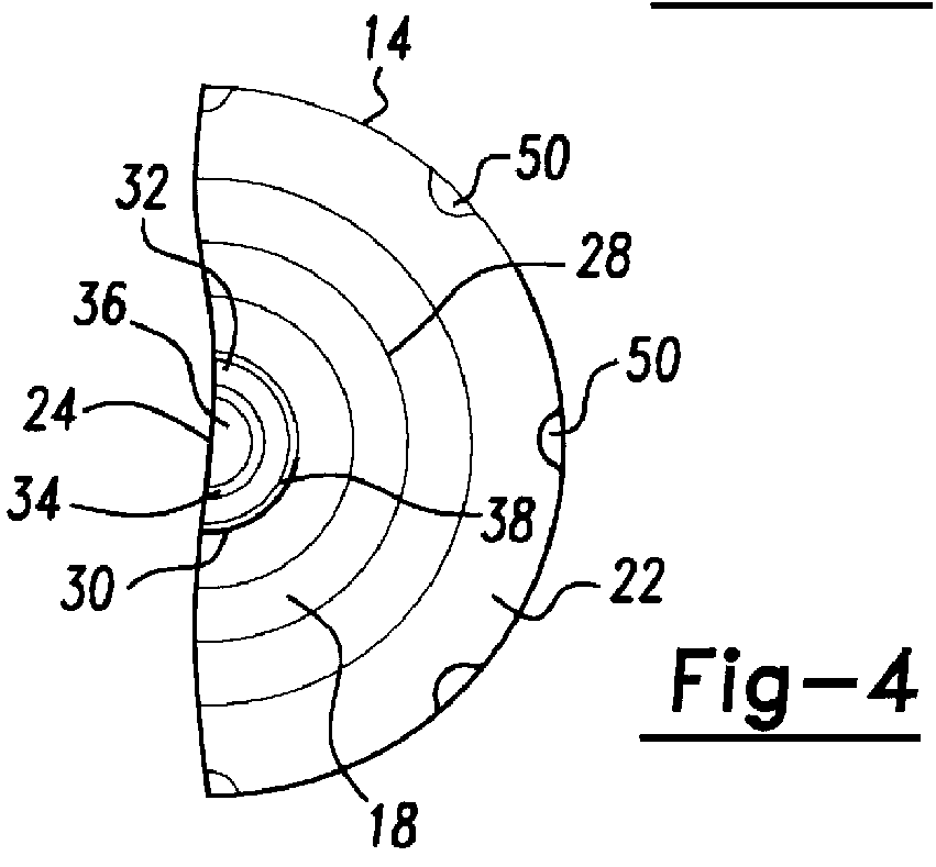
In all Figures the corresponding reference numerals are used for same part or parts which have the same function. Moreover, in all Figures in which only the right hand half of the respective embodiment is shown it should be assumed that the left hand half is designed with mirror-symmetry to the right hand half and is only being omitted for the sake of the illustration.

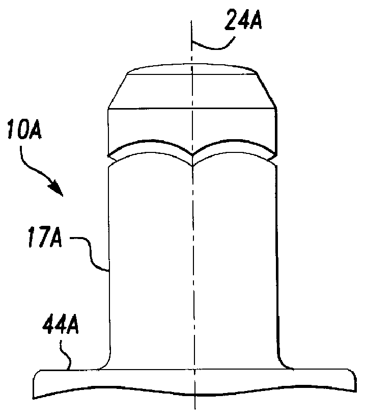
FIGS. 1 and 2 show, first of all, a functional element 10 with a shaft part 12 and a head part 14. As can be seen from FIG. 1, the shaft part 12 is provided here with a thread 16. This is, however, required as is shown in FIG. 1A, the shaft part 12 can, for example, be realized simply as a cylindrical shaft 17A. The shaft part can be fashioned in any desired manner, depending on the element with which the functional element 10 is to cooperate.

The head part 14 of this element is of hollow shape, i.e. it has a hollow cavity 18 and it is formed in its lower region in FIG. 1 in accordance with the nut element of the above-...


PUM

PropertyMeasurementUnit
polygonal shapeaaaaaaaaaa
axial forcesaaaaaaaaaa
corrosionaaaaaaaaaa

Abstract

A functional element comprising a shaft part and a head part, or a hollow body part, for attachment to a sheet metal part, in particular for liquid-tight and / or gas-tight attachment to the sheet metal part, without penetrating or perforating the sheet metal part, is characterized in that the head or body part has at least one undercut feature either in an open hollow cavity at its end face confronting the sheet metal part and / or at its outer periphery and is formed in the regions which enter into contact with the sheet metal part with exclusively rounded shaping edges which, during the insertion of the element, cooperate with a shaping die button in order to provide a hooked engagement in form-fitted manner of the sheet metal material, with the undercut feature or with the undercut features. A method of attaching a functional element to a sheet metal part, a component assembly and also at least one die button and a setting head are disclosed and claimed.

Description

The present invention relates to a method for the sealed attachment, in particular for the liquid-tight and / or gas-tight attachment of a functional element, in particular of a functional element having a head part and a functional part, to a sheet metal part in which the element does not penetrate through the sheet material but is secured to the sheet metal part for the transmission of axial forces and preferably also of torques. Furthermore, the present invention relates to a functional element, to a component assembly comprising the functional element and a sheet metal part, and also to a die button and to a setting head for use in the method of attaching a functional element to the sheet metal part.DESCRIPTION OF PRIOR ARTIn the construction of vehicle bodies in particular, but not exclusively, the need frequently exists to provide an absolutely liquid-tight and preferably also gas-tight connection between a sheet metal part and a functional element having a shaft part and a head...

Claims


Application Information

Patent Timeline
Patent Type & Authority Patents(United States)
IPC IPC(8): B23P19/06F16B37/04F16B37/06
CPCF16B37/068B23P19/062
Inventor MULLER, RUDOLF
Owner HVB BANQUE LUXEMBOURG
Why Eureka
Try Eureka