Shooting video game machine

a video game machine and video game technology, applied in the field of shooting video game machines, can solve the problems of complex structure of the position detection unit, degrading the quality of the screen image, and increasing the cost of the shooting video game machines as a whol

Inactive Publication Date: 2000-11-14
KONAMI DIGITAL ENTERTAINMENT CO LTD
View PDF8 Cites 318 Cited by
  • Summary
  • Abstract
  • Description
  • Claims
  • Application Information

AI Technical Summary

Problems solved by technology

As a result, the quality of the screen image is degraded.
Therefore, structure of the positio

Method used


Image

  • Shooting video game machine
  • Shooting video game machine
  • Shooting video game machine

Examples


Embodiment Construction

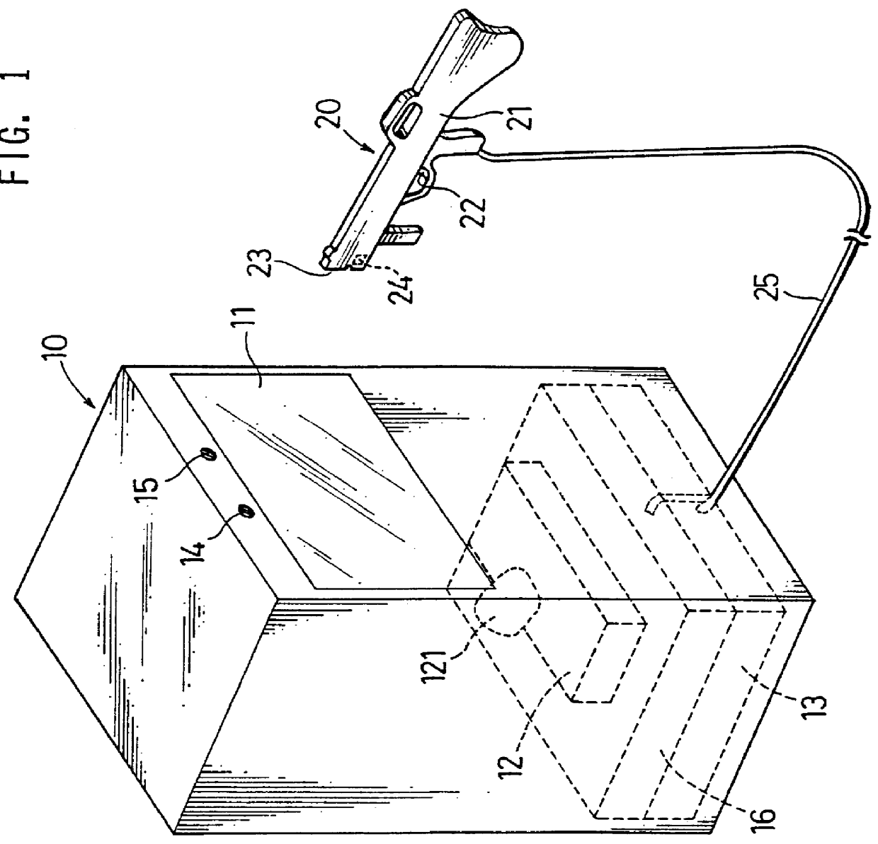
FIG. 1 is a perspective view showing a structure of a shooting video game machine of an embodiment of the present invention. In FIG. 1, the shooting video game machine includes of a game machine main unit 10 and a mock gun 20.

The game machine main unit 10 has a monitor screen 11, a projector 12 for projecting game image on the monitor screen 11, and a game controller 13 for processing a game in accordance with programs stored in a ROM and shooting results of the mock gun 20, and transmitting image signals to the projector 12. In addition, the game machine main unit 10 has a pair of light sources 14, 15 arranged at certain positions slightly above an upper boundary of the monitor screen 11 and a position detection unit 16 arranged proximate to the game controller 13. The light sources 14, 15 each produce infrared spot light having a wave length which is out of human-viewable-range. The position detection unit 16 detects a hit position of the mock gun 20. It should be noted that herei...


PUM


Abstract

A shooting video game machine includes a monitor screen, a light source near the monitor screen, and a mock gun having an image sensor with a pixel array for capturing an image including the monitor screen and the light source. A light source position detection unit detects as image position of an image of the light source in the pixel array. A hit position detection unit for determines a position aimed at on the monitor screen based on the image position. The light source position detection unit includes a detector for detecting pixels having data of the image of the light source and stores only address of the detect pixels to a memory. A light source position calculator calculate the image position of the light source according to the address data stored in the memory in a certain time period.

Description

BACKGROUND OF THE INVENTION AND RELATED ART STATEMENTThis invention relates to a shooting video game machine having a monitor screen which displays target characters and a mock gun which aims at and shoots the character(s) displayed on the monitor screen.Conventionally, the shooting video game machine of this type includes a mock gun having a muzzle, a trigger, and a light receiving element arranged on the muzzle and a monitor screen such as a projector having a CRT for projecting game.Such shooting video game machine is constructed such that when the trigger is pulled, a so-called white screen made only by emission lines by a raster scanning for one frame and the light receiving element receives a light produced during the raster scanning and then a hit position (or a point of impact) by the mock gun is detected by a time elapsed from the beginning of the raster scanning to the time when the light is received by the light receiving element of the mock gun. Thereafter, the judgment ...

Claims


Application Information

Patent Timeline
IPC IPC(8): A63F13/04A63F13/02F41G3/26F41G3/00
CPCA63F13/04F41G3/2661F41G3/2633A63F2300/1087A63F2300/8076A63F13/837A63F2300/638A63F13/426A63F13/219A63F13/44A63F13/213
Inventor KOBAYASHI, TATSUYA
Owner KONAMI DIGITAL ENTERTAINMENT CO LTD
Why Eureka
Try Eureka