Determining electrical conductivity of a laminated earth formation using induction logging

a technology of induction logging and laminated earth, which is applied in the direction of seismology for water logging, using reradiation, instruments, etc., can solve the problems of difficult interpretation of the transversal induction logging tool response, difficult to detect hydrocarbon-bearing zones in laminated clastic reservoirs, and the logs obtained by using this tool are rather "wild"

Inactive Publication Date: 2000-11-14
SHELL OIL CO
View PDF3 Cites 179 Cited by
  • Summary
  • Abstract
  • Description
  • Claims
  • Application Information

AI Technical Summary

Problems solved by technology

In general, hydrocarbon-bearing zones are difficult to detect in laminated clastic reservoirs consisting of alternating thin layers of shale and sand, when using a conventional induction logging tool.
However, the response of the transversal induction logging tool is difficult to interpret because its response suffers from large borehole-effects and wellbore fluid invasion-effects.
However, the logs obtained when using this tool are rather "wild" and are therefore difficult to interpret.
This problem becomes even more manifest when the tool is run through a sequence of earth layers.

Method used


Image

  • Determining electrical conductivity of a laminated earth formation using induction logging
  • Determining electrical conductivity of a laminated earth formation using induction logging

Examples


Embodiment Construction

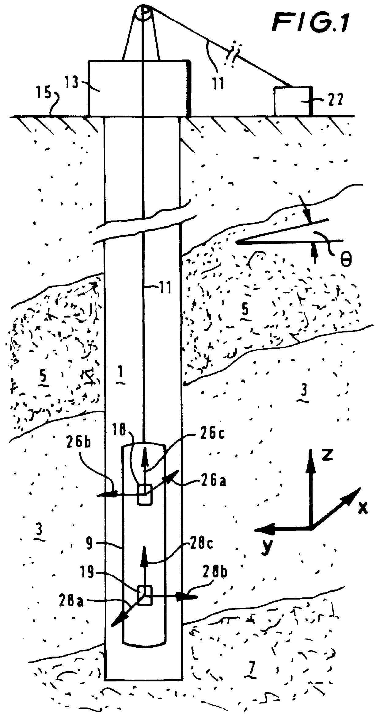
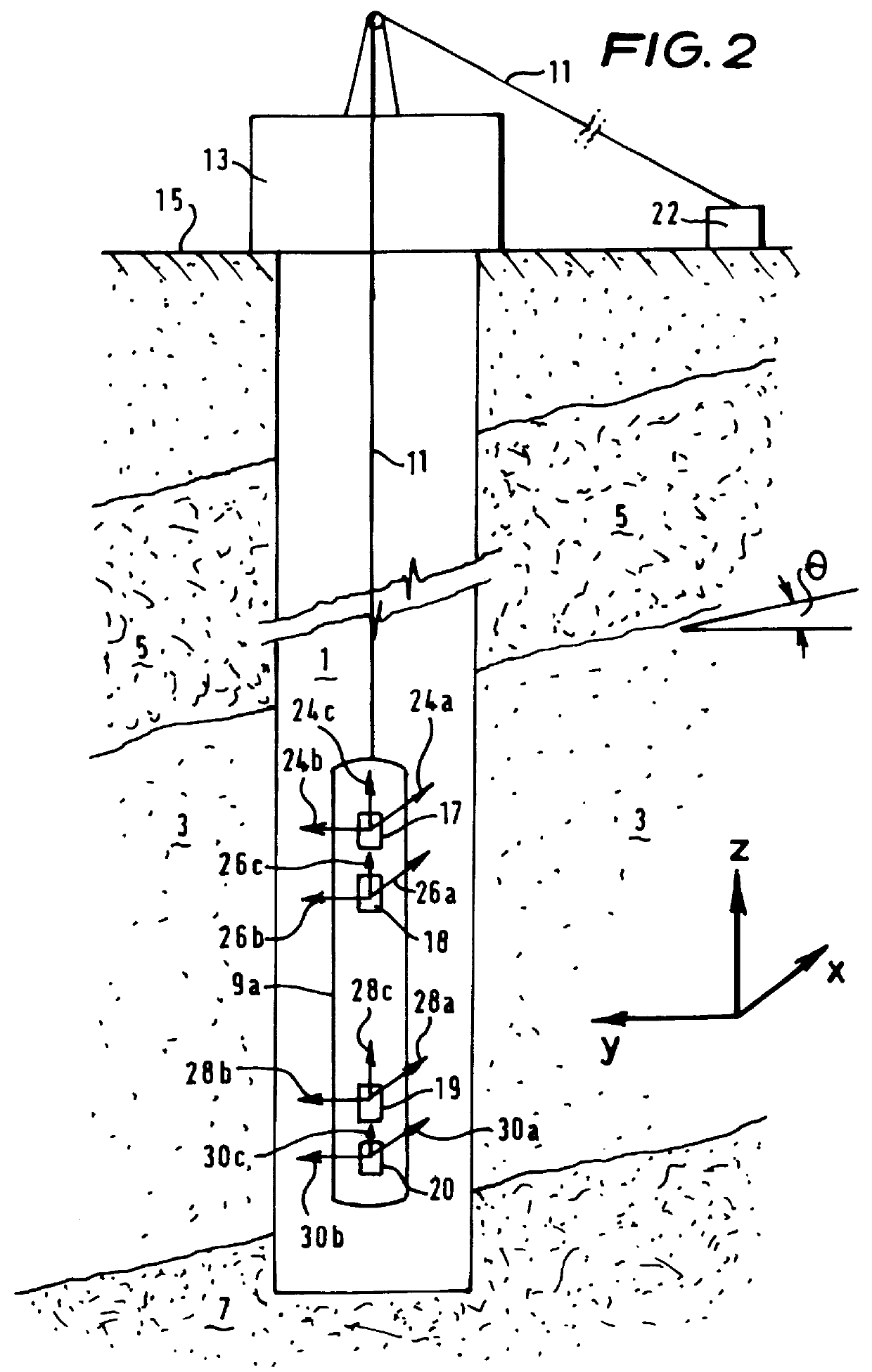
The wellbore 1 in FIG. 1 extends into an earth formation which includes a hydrocarbon-bearing sand layer 3 located between an upper shale layer 5 and a lower shale layer 7, the shale layers 5, 7 having a higher conductivity than the hydrocarbon bearing sand layer 3. An induction logging tool 9 used in the practice of the invention has been lowered into the wellbore 1 via a wireline 11 extending through a blowout preventor 13 (shown schematically) located at the earth surface 15. The relative orientation of the wellbore 1 and the logging tool 9 with respect to the layers 3, 5, 7 is determined by two angles, one of which (.theta.) is shown in the Figure. The logging tool 9 is provided with a set of transmitter coils 18 and a set of receiver coils 19, each set of coils 18, 19 being connected to surface equipment 22 via suitable conductors (not shown) extending along the wireline 11. The surface equipment 22 includes an electric power supply to provide electric power to the set of coils...


PUM


Abstract

A method is provided for determining an electric conductivity of an earth formation formed of different earth layers, which earth formation is penetrated by a wellbore containing a wellbore fluid, is provided. The method includes the steps of: lowering an induction logging tool into the wellbore to a location surrounded by a selected one of the earth layers, the tool having a magnetic field transmitter effective to induce magnetic fields of different frequencies in the earth formation, and a magnetic field receiver effective to receive response magnetic fields and to provide a signal representative of each response magnetic field, at least one of the transmitter and the receiver having a plurality of magnetic dipole moments in mutually orthogonal directions. At least two of the different frequencies are selected, and for each selected frequency, the transmitter is operated so as to induce a magnetic field in the earth formation and the receiver is operated so as to provide a signal representing a response magnetic field, wherein the at least one of the transmitter and receiver is operated in the mutually orthogonal directions. The signals are combined in a manner so as to create a combined signal having a reduced dependency on the electric conductivity in the wellbore region. The formation resistivity and the relative orientation of the logging tool with respect to the formation layering is determined from the combined signal.

Description

The present invention relates to a method of determining electric conductivity of an earth formation formed of different earth layers, whereby a wellbore containing a wellbore fluid extends into the earth formation.BACKGROUND TO THE INVENTIONIn general, hydrocarbon-bearing zones are difficult to detect in laminated clastic reservoirs consisting of alternating thin layers of shale and sand, when using a conventional induction logging tool. If the layers are too thin to be detected individually by the induction logging tool because the vertical resolution of the tool is too low, the tool reads an average conductivity of the formation. In a vertical borehole, a conventional induction logging tool with the magnetic dipole moments in vertical direction reads an average conductivity which is a combination of the sand- and shale conductivities, but which is dominated by the relatively high conductivity of shale layers. A transversal induction logging tool with the magnetic dipole moments i...

Claims


Application Information

Patent Timeline
Patent Type & Authority Patents(United States)
IPC IPC(8): G01V3/28G01V3/18
CPCG01V3/28
Inventor STRACK, KURT-MARTINTABAROVSKY, LEONTY ABRAHAMBEAR, DAVID RONALDVAN DER HORST, MELIS
Owner SHELL OIL CO
Why Eureka
Try Eureka