Relative gravity of structures

Inactive Publication Date: 2000-11-28
LAZARS ENG
View PDF6 Cites 17 Cited by
  • Summary
  • Abstract
  • Description
  • Claims
  • Application Information

AI Technical Summary

Problems solved by technology

But as evidences show, collected from the earthquakes happened in the past throughout the world, where building structures are constructed of a various materials(lightweight, heavyweight or materials having a various degree of a strength), no building structures have displayed capability to withstand forces induced by earthquakes without being subjected to a severe damage or destruction.
Accordingly, lightweight materials, such as wood, used in construction of dwelling houses and offices, are most vulnerable to damage caused by high wind since generally have relatively small resistance to high wind, everything else being equal.
In fact, many structures constructed in the United States are made of wood and other lightweight materials and therefore are vulnerable to high wind.
When such lightweight structures are subjected to high wind, their weight becomes extremely small and easy moveable by the horizontal force.
1. The gravity resultant of the structure is displaced from its natural position in direct proportion to the intensity of the wind speed. This causes severe disturbances in the structure's ability t

Method used


Image

  • Relative gravity of structures
  • Relative gravity of structures
  • Relative gravity of structures

Examples


Embodiment Construction

It is seen from TABLE NO.5, columns 3 and 4 that if reactive effects of relative gravity were included the amplitudes of displacement under wind load and seismic load action would approach zero, means the structure is in the state of a superior stability.

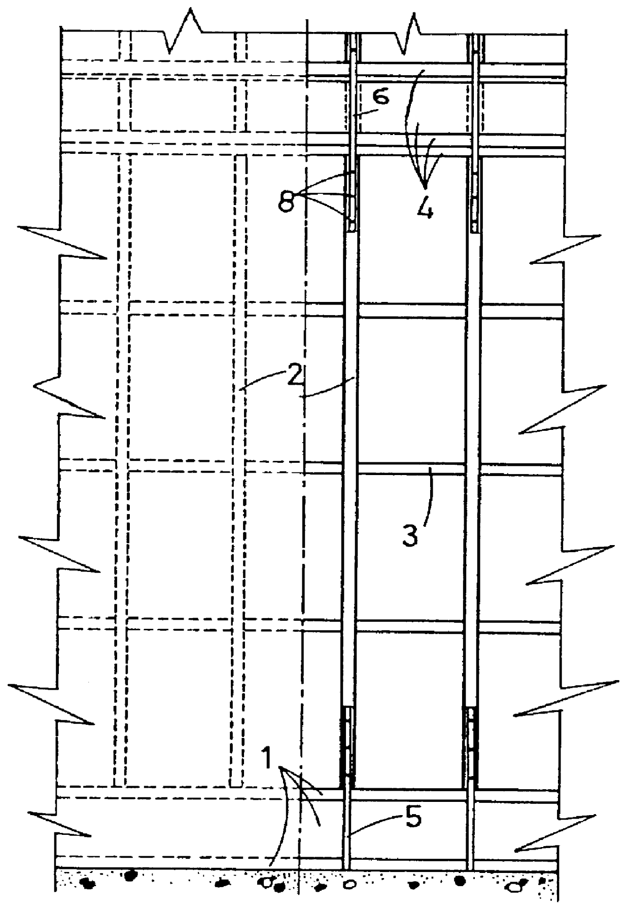
Note that in this particular analytic testing of a wall structure of the present invention, the wall unit is taken as Lambda=2 feet wide whereas the wall unit of the prior art shown in FIG. 8 and TABLE NO.2 was taken as Lambda=1.33 feet(16 inches) wide. In general, the width of the wall(Lambda) is arbitrary.

Analytical testing of the structure given in the prior art and the structure of the present invention was made for the three story structures of FIGS. 3 and 11 having a size of 20 feet by 20 feet in a plan (i.e. width and length). However, the results depicted in TABLE NOS. 1-5 would be almost the same for any size building structure. Gravity displacement of a structure is greater for a greater area of a structure that is under w...


PUM


Abstract

A construction modification and associated method used in pre-stressed building structures is designed to enhance resistance to extreme high wind environments, such as hurricanes and tornadoes, and in earthquake prone regions is most useful for structures built of lightweight materials such as wood or aluminum but is also applicable to structures built of heavy materials such as brick, stone, concrete, reinforced concrete and steel. Modifications include increased spacing of the wall frame elements, namely wall studs or columns, symmetrical sheeting at both sides of the frame when wood is used to build wall panels or symmetrical building of walls inside the frame when heavy material as brick, concrete block, stone, cast concrete etc. are used to build panels, a new incorporated into structures is complement system of strings and balance beams and modification of the effective weight or gravity of the structure. The strings of the complement system are placed in channels running through the wood studs of wood wall panels (or columns of the frame system or massive walls if other heavy materials herein mentioned are used) and a balance beam is placed at the top of the walls of each story. A pre-stressing forces are supplied to the strings at the top of each story by a hydraulic devices or other mechanical means in direction coinciding with the direction of the structure's natural gravity. The balance beam distributes applied forces uniformly on the walls. The additional energy in the wall structure, called relative gravity, eliminates problems associated and caused by wind loads and seismic loads including intense vibration of walls, tension and uplift forces in structure, structure's instability and the other modifications eliminates the presence of anemic connectors and fasteners as the means in prior art for load transfer throughout the structure.

Description

BACKGROUND OF INVENTIONThis invention involves a method and its associated building support structures for the modification and improvement of building construction, in particular for the modification of the construction of buildings with respect to resistance to strong winds and earthquakes in earthquake prone regions.This invention is especially directed to, although not exclusively directed to, residential and office buildings that are composed of and are built using standardized structural elements and units that as wall units, floor units and roof units, that are constructed of lightweight material as well as of heavy weight material.For buildings that are located in areas in which "high wind(s)" occur, designed herein as wind speeds of 130 to 350 miles per hour("mph"), it is essential that the building be constructed so that it is capable of resisting such wind speeds without being damaged or destroyed. It should be noted that wind speeds of 130 to 350 mph occur in hurricanes,...

Claims


Application Information

Patent Timeline
IPC IPC(8): E04B1/10E04B1/02E04H9/14E04B1/00E04B1/35
CPCE04B1/10E04H9/14E04B2001/3583E04B2001/2684
Inventor KOVACHEVICH, LAZAR S
Owner LAZARS ENG
Why Eureka
Try Eureka