Air temperature control system for a vehicle

Inactive Publication Date: 2000-11-28
DENSO CORP
View PDF12 Cites 64 Cited by
  • Summary
  • Abstract
  • Description
  • Claims
  • Application Information

AI Technical Summary

Problems solved by technology

However, in the aforementioned air conditioning unit, when the outside air temperature is in an intermediate region, between 10 and 20.degree. C., for example, a problem occurs.
At this time, after wind airflow based on the temperature is generated by the rear evaporator, a foul smell is emitted due to the dust and mold in the rear evaporator and oxide caused by the corrosion of the rear evaporator, thereby giving passengers in the vehicle compartment an unpleasant feelin

Method used


Image

  • Air temperature control system for a vehicle
  • Air temperature control system for a vehicle
  • Air temperature control system for a vehicle

Examples


Embodiment Construction

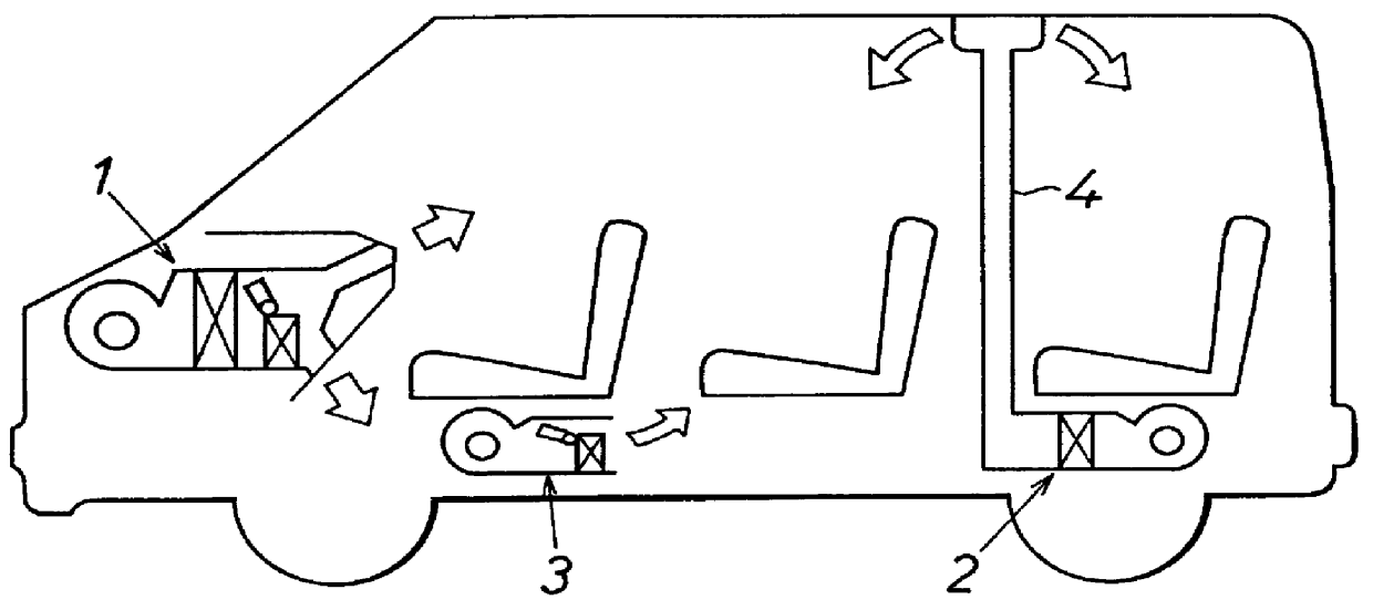
An embodiment of the present invention will hereinafter be described with respect to the accompanying drawings. As shown in FIG. 1, a front air temperature control unit 1 for cooling and heating a front seat area is disposed at the front seat side of a vehicle. A rear cooling unit 2 for cooling a rear seat area and a rear heater unit 3 for heating the rear seat area are disposed at the rear side thereof.

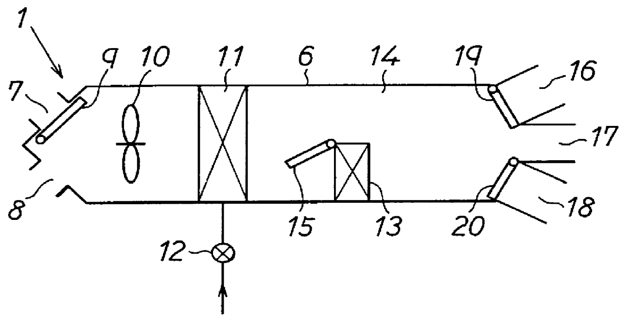
Front air conditioning unit 1 is provided at an inside of a vehicle instrument panel disposed at the vehicle front seat side. Air is blown from a position toward the upper part of the body and the feet of the passenger at the front seat and also toward an inner surface of a windshield.

Rear cooler unit 2 is provided at a space between a inner wall of the vehicle and the bottom of the rear seat so that air is blown primarily toward the head of a passenger in the rear seat from the vehicle ceiling via a ceiling duct 4.

Rear heater unit 3 is provided at a bottom portion of the front passe...


PUM


Abstract

When target blowout temperature to the inside of a vehicle is over a predetermined temperature in, an air temperature control system according to the present invention controls a cooling-ability controller to control air temperature of air cooled by a heat exchanger for cooling so that airflow becomes a predetermined temperature, and reduces the amount of blowout air into the vehicle per unit time compared with the amount of the blowout air when the target blowout temperature is under the predetermined temperature. Accordingly, the cooling air temperature due to the heat exchanger for cooling is fixed at the predetermined temperature even when the target blowout temperature is over the predetermined temperature. Therefore, generation of malodors due to dust and mold in the heat exchanger for cooling is prevented.

Description

The present application is related to and claims priority from Japanese Patent Application No. Hei 7-337143, incorporated herein by reference.1. Field of the InventionThe present invention relates to an air temperature control system for a vehicle for controlling a cooling unit cooling the inside of the vehicle or a heating unit heating the inside of the vehicle.2. Description of Related ArtAn air temperature control system for a vehicle for controlling air conditioning or heating units in order to cool the vehicle's rear seat area by means of a rear cooling unit and to heat the rear seat area by means of a rear heating unit is disclosed in Japanese Patent Number B2 258126. More specifically, a required quantity of heat Q.sup.R is determined for maintaining the rear seat air temperature at a predetermined rear seat air temperature. When the required quantity of heat Q.sup.R is negative, the rear cooling unit starts cooling the rear seat air with the rear heating unit turned off. Whe...

Claims


Application Information

Patent Timeline
IPC IPC(8): B60H1/00B60H1/24
CPCB60H1/00064B60H1/247B60H1/00207B60H2001/002
Inventor ITO, YUJIKAWAI, TAKAYOSHI
Owner DENSO CORP
Why Eureka
Try Eureka