Sealing device

a sealing device and labyrinth technology, applied in the direction of engine sealing, closures, packaging, etc., can solve the problems of unsuitable sealing, unsuitable sealing, and difficulty in avoiding a certain flow through the labyrinth

Inactive Publication Date: 2000-12-05
ALFA LAVAL AB
View PDF12 Cites 53 Cited by
  • Summary
  • Abstract
  • Description
  • Claims
  • Application Information

AI Technical Summary

Benefits of technology

By such sealing elements a very good sealing function is obtained since they give a very great flow resistance to the medium which is to be prevented from passing the sealing device. Furthermore, by such sealing elements, a pumping action may be obtained by providing the sealing elements non-symmetrically. Consequently, the sealing device according to the invention gives a possibility to counteract a flow due to a pressure difference between the spaces delimited by the sealing device or to provide a flow between these spaces in a desired direction. Furthermore, the medium which in the actual case passes through the sealing device will be forced into a complicated path in such a manner that a great pressure drop arises across the sealing device. In addition, it is possible to separate possible liquid droplets or particles present in a medium and penetrating the sealing device, since these particles or droplets are captured in the first chamber and displaced radially outwardly by the centrifugal force and collected in the radially outward portion of the chamber. Thus, the sealing device according to the invention prevents very effectively particles and / or liquid droplets from passing through the sealing device.

Problems solved by technology

In many technical constructions and applications, it is a problem to provide a sealing which is sufficiently good due to the clearances which have to exist between two members being rotatable relative to each other.
Due to the high number of revolutions of the driving shaft and its frequently large radial movements, lip sealings or other abutting machine sealings may not be used, but contact free sealing devices such as labyrinth sealings are often the only alternative.
In addition, since there may be a pressure difference between said space and the surroundings, it is very difficult to avoid a certain flow through the labyrinth sealing.
This means that unwanted particles and liquids will be transported by the flow.
Furthermore, this document discloses the arrangement that the flanges of the rotor are provided with projecting sealing portions, the outer ends of which are located very close to the turbine part, making the sealing disclosed inappropriate when relatively radial movements occur between the rotating and stationary parts.
Furthermore, by such sealing elements, a pumping action may be obtained by providing the sealing elements non-symmetrically.
Furthermore, the medium which in the actual case passes through the sealing device will be forced into a complicated path in such a manner that a great pressure drop arises across the sealing device.

Method used


Image

  • Sealing device
  • Sealing device
  • Sealing device

Examples


second embodiment

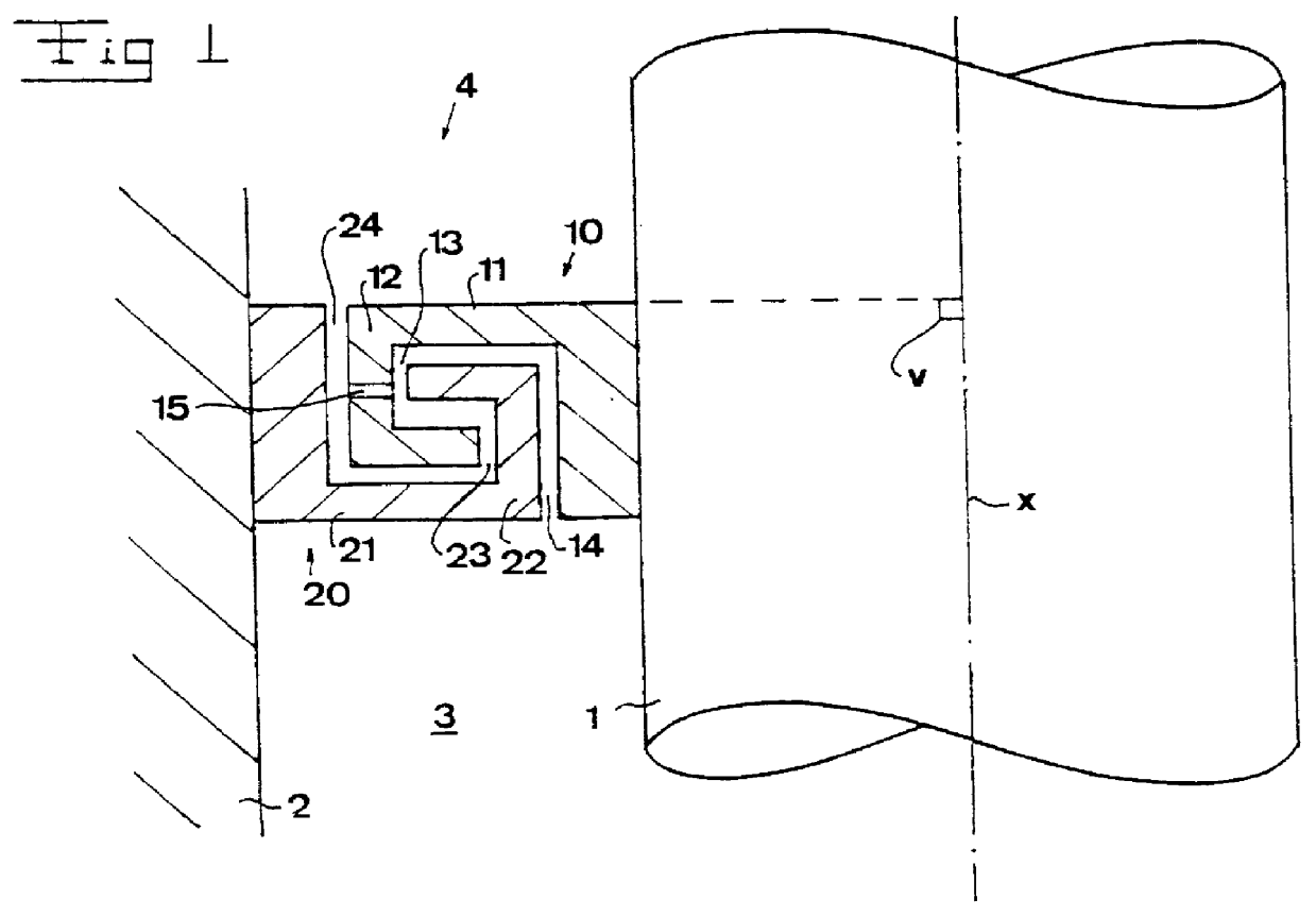
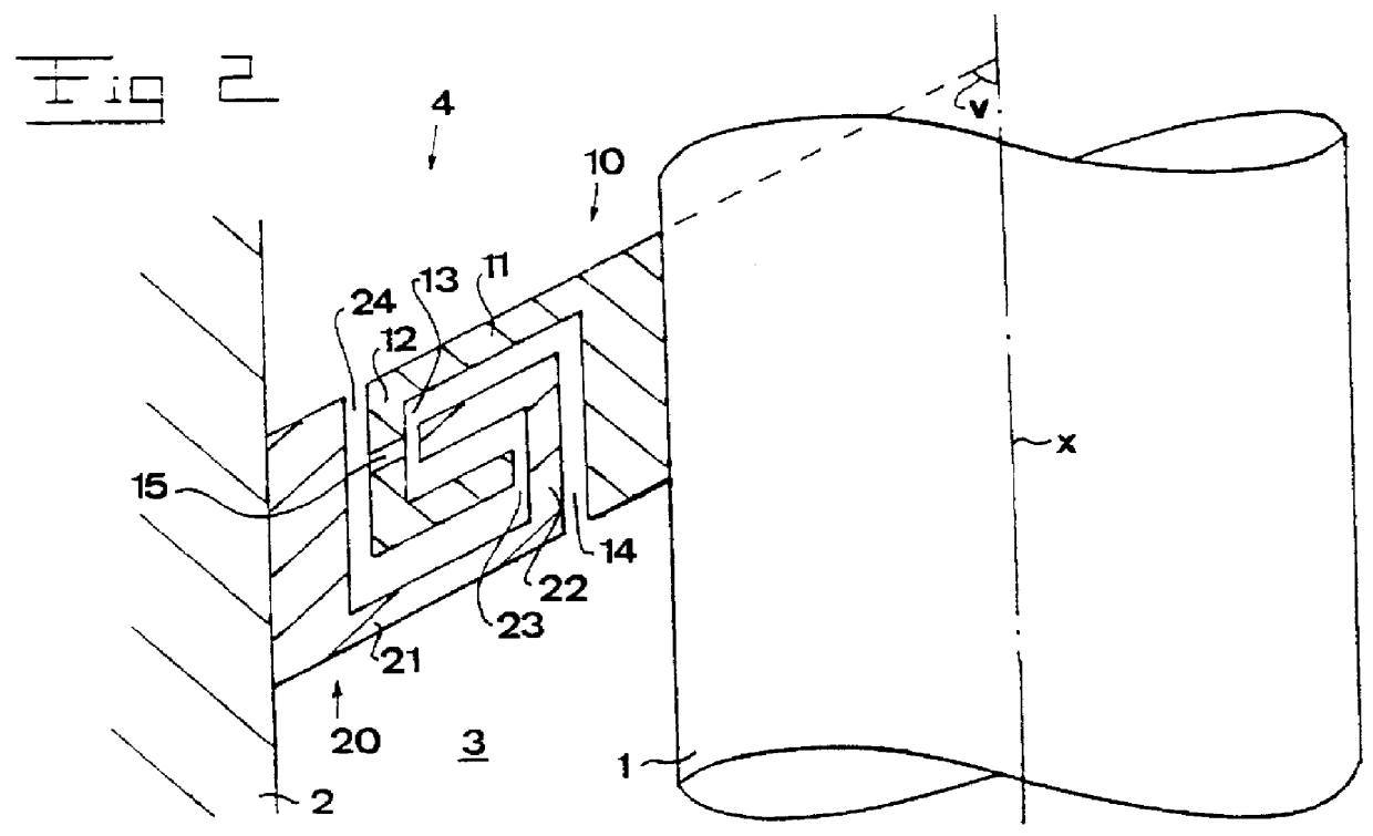
FIG. 2 discloses the invention, which is similar to the one in FIG. 1 but having an angle v being acute. It is to be noted that for elements having a corresponding function, the same reference signs have been used in all disclosed embodiments of the sealing device. The surfaces of the essentially radial portions and the surfaces of the attachment members 11 and 21 all comprise an essentially rectilinear generatrice intersecting the axis of rotation x by a common angle v. The angle v is in the embodiment disclosed in FIG. 2 about equal to 60.degree.. However, it is to be noted that this angle may vary from greater than 0.degree. to less than 180.degree.. It is also to be noted that the generatrice according to alternative embodiments may be curved.

The embodiments disclosed in FIGS. 1 and 2 comprise a non-symmetrical sealing device 4, i.e. it seals essentially in one direction. Furthermore, it is possible to provide a pumping action by such a non-symmetrical embodiment, i.e. the seali...

third embodiment

FIG. 3 discloses the sealing device 4, which comprises sealing elements 10 and 20 which are essentially identical to those disclosed in FIG. 2, and a third sealing element 30 which is fixedly provided at the shaft 1 axially beside the second sealing element 20 and comprising a conical disk or flange 31 extending around the shaft 1 and radially outwardly from the axis of rotation x by the same conical angle v as the conical parts of the sealing elements 10 and 20. Thanks to the third sealing element 30 the non-symmetrical construction or function of the sealing device 4 is reduced in comparison with the embodiments disclosed in FIGS. 1 and 2. This means that the pumping action of the sealing device 4 disclosed in FIG. 3 is relatively small at the same time as it effectively will capture liquid droplets and / or particles and thus prevent these from passing the passage from above and downwardly.

fourth embodiment

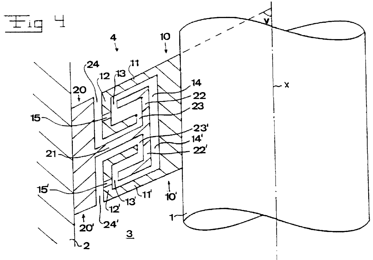
FIG. 4 discloses the sealing device according to the invention with two pairs of sealing elements 10, 20, and 10', 20' symmetrically provided. The two pairs are provided in such a manner that the annular gaps 14 and 14+, and 24 and 24+, respectively, enclosing the axis of rotation, are located opposite to each other. Thus, the sealing elements 10 and 10' comprise a respective conical attachment member 11 and 11' having a respective flange member 12 and 12'. Each of the flange members 12 and 12' comprise a circular cylindrical portion and a conical portion, which form an annular third chamber 13' enclosing the axis of rotation x. The circular cylindrical portions of the flange members 12 and 12' both comprise drainage holes 15 and 15'. The sealing elements 20 and 20' have a common attachment member 21 from which two flange members 22 and 22' extend by a respective circular cylindrical portion and a respective conical portion and thus form a second annular chamber 23 enclosing the axi...


PUM


Abstract

A sealing device (4) is provided for sealing between a first member (1) and a second member (2) and comprises a first sealing element (10), provided on the first member and extending thereabout towards the second member, and a second sealing element (20), provided on the second member and extending towards the first member without direct contact with the first sealing element (10). The first sealing element (10) comprises a first flange member (12) extending towards the first member (1) forming a first chamber (13) and the second sealing element (20) comprises a second flange member (22) extending towards the second member (2) and forming a second chamber (23). The flange members (12, 22) are provided overlapping each other in such a manner that the first flange member (12) extends in the second chamber (23) and the second flange member (22) extends in the first chamber (13).

Description

THE BACKGROUND OF THE INVENTION AND PRIOR ARTThe present invention refers to sealing devices of the labyrinth type, i.e. co-operating sealing elements are not abutting each other but there is a gap therebetween. In particular, the invention refers to a sealing device for sealing a gap between a first member and a second member, the first member being rotatable in relation to the second member about an axis of rotation, and one of the two members forming a cavity within itself, in which the other of the two members extends axially and thereby forms said gap between the two members, the sealing device comprising a first sealing element, having a first attachment member arranged to be fixedly provided on the first member and extend around the axis of rotation and from the first member extend towards the second member, and a second sealing element, having a second attachment member arranged to be fixedly provided on the second member and extend around the axis of rotation and from the s...

Claims


Application Information

Patent Timeline
Patent Type & Authority Patents(United States)
IPC IPC(8): F16J15/447F16J15/44
CPCF16J15/4474Y10S277/928B04B9/12
Inventor BORGSTROM, LEONARDCARLSSON, CLAES GORANFRANZEN, PETERINGE, CLAESLAGERSTEDT, TORGNYMOBERG, HANSSZEPESSY, STEFANSUNDSTROM, MIKAEL
Owner ALFA LAVAL AB
Why Eureka
Try Eureka