

Transmit-receive system and transmission method, in particular for a mobile telephone
a technology of transmit-receive system and transmission method, which is applied in the field of mobile telephones, can solve problems such as unsatisfactory solutions of the above kind, and achieve the effects of less noise, increased reliability, and enormous reduction of costs
- Summary
- Abstract
- Description
- Claims
- Application Information
AI Technical Summary
Benefits of technology
Problems solved by technology
Method used
Image

Examples
Embodiment Construction
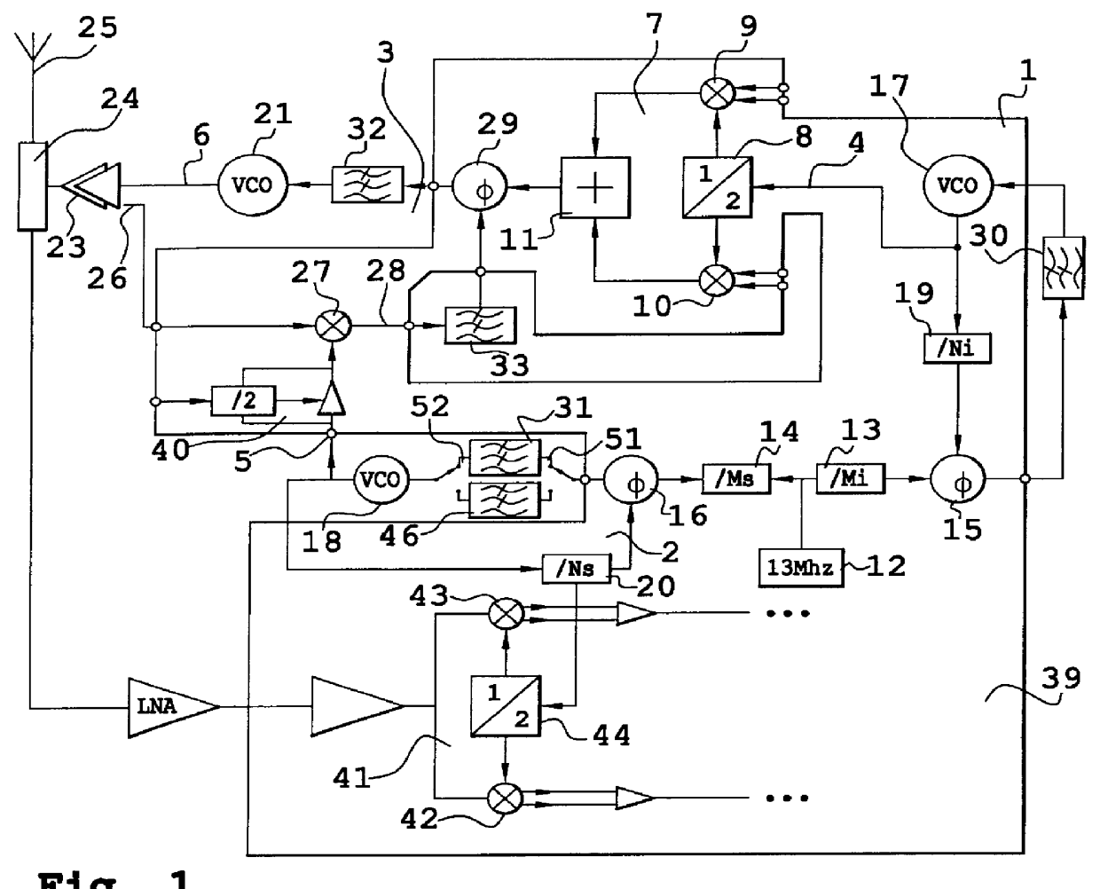
FIG. 1 shows a transmission system in accordance with the invention. The system is intended to be used in the field of mobile telephony in particular. It includes three phase-locked loops 1 to 3. The first loop 1 is an intermediate frequency loop and produces at its output 4 a signal at an intermediate frequency. The second loop 2 is a translation frequency loop and produces at its output 5 a signal at a translation frequency. The third loop is a transmit loop and produces at its output 6 a signal at a transmit frequency. In one example, the signal available at the output 4 has a frequency in the order of 100 MHz and that available at the output 5 has a frequency in the order of 1,700 MHz. The value of the transmit frequency is thus formed additively from the values of the intermediate and translation frequencies. In the DCS, the transmit frequency is in the order of 1,800 MHz (it varies with the frequencies allocated to a given telecommunication operator). In the GSM, these values ...
PUM
 Abstract
Description
Claims
Application Information