Variable gain amplifier

a gain amplifier and variable gain technology, applied in the direction of instruments, electric/magnetic computing, computation using denominational number representation, etc., can solve the problems of insufficient operation voltage, dc design becomes difficult, and malfunctions are possibl

Inactive Publication Date: 2000-12-19
FUJITSU LTD
View PDF5 Cites 77 Cited by
  • Summary
  • Abstract
  • Description
  • Claims
  • Application Information

AI Technical Summary

Problems solved by technology

Accordingly, the gain variation is not monotonous for the variation of the bias current ratio .alpha., i.e. the variation of the gain control signal input, so that when the gain fall is required, the gain will rise, resulting in a possibility of malfunction.
Therefore, it is disadvantageous that as the number of transistors connected in cascade increases, a sufficient operation voltage is not secured and a DC design becomes difficult.

Method used


Image

  • Variable gain amplifier
  • Variable gain amplifier
  • Variable gain amplifier

Examples


Embodiment Construction

Hereinafter, embodiments of a variable gain amplifier according to the present invention will be described referring to attached drawings.

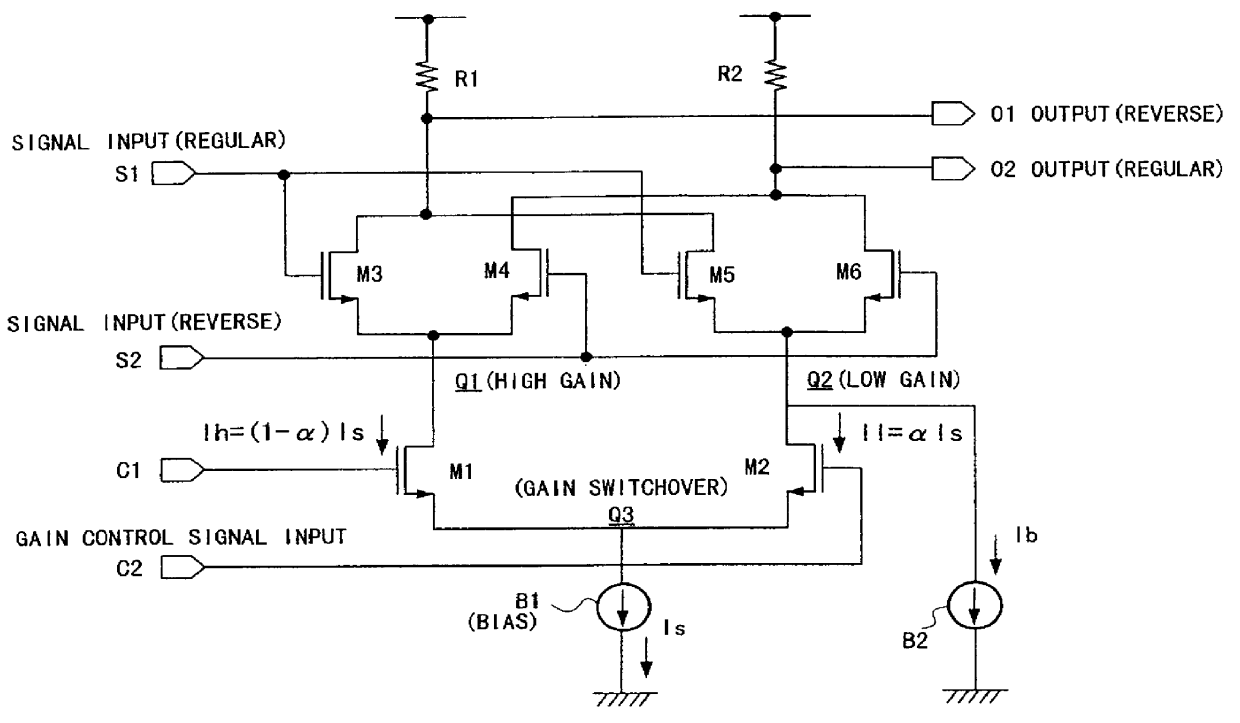
FIG. 1 shows an embodiment (1) of a variable gain amplifier according to the present invention. In this embodiment, as compared with the prior art shown in FIG. 14, a fixed current source B2 is provided at a source coupling portion between transistors M5 and M6 in order that an offset fixed current Ib flows through the side of the transistors M5 and M6 in a low gain differential amplifier Q2.

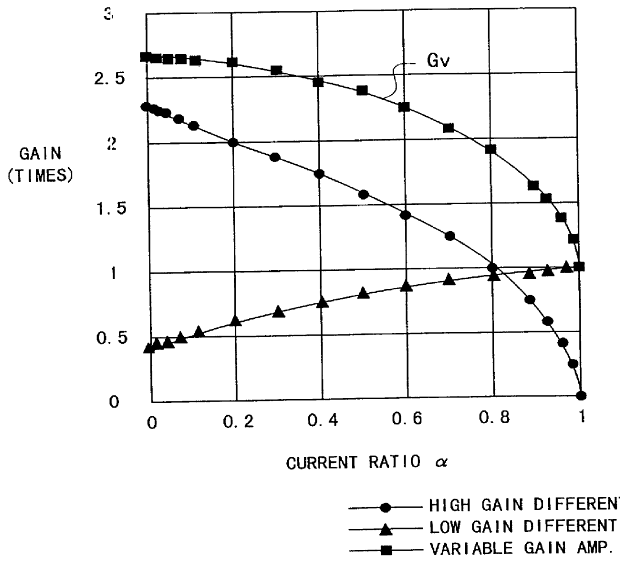
A current switchover of transistors M1 and M2 in a gain control differential amplifier Q3 in this arrangement prevents the transistors M5 and M6 in the low gain differential amplifier Q2 from rapidly rising as shown in FIG. 15, suppresses the gain variation of the low differential amplifier Q2 equal to or lower than that of a high gain differential amplifier Q1 as shown in FIG. 2, and monotones the gain variation of the variable gain amplifier in its entirety....


PUM


Abstract

In a variable gain amplifier controlling a gain by using differential amplifiers with a gain control signal, a gain switchover differential amplifier or a bias circuit which composes a current mirror with the gain switchover differential amplifier is connected between a high and a low gain differential amplifier for the same bias current which are mutually connected to share load resistances for the same output polarity and a bias current source common to both of the differential amplifiers, to perform switchover operations of the high and the low differential amplifier by a gain control signal, and a current source which flows a fixed offset current through at least the low one of the high and the low differential amplifier is provided.

Description

1. Field of the InventionThe present invention relates to a variable gain amplifier, and in particular to a variable gain amplifier controlling a gain with a differential amplifier by a gain control signal.The variable gain amplifier is utilized in many devices using electric circuits regardless of technical fields. When an extension of an input dynamic range is intended for the sake of circuit designs, it is required to be used not only as a simple variable gain amplifier but also, for instance, as a linear amplifier for a small signal input, as a variable gain amplifier for a middle signal input or as an amplitude limiting amplifier for a large signal input.2. Description of the Related ArtFIG. 14 shows an arrangement of a conventional variable gain amplifier. This variable gain amplifier is composed of two differential amplifiers Q1 and Q2 sharing load resistors R1 and R2, a differential amplifier Q3 to perform a gain switchover of the differential amplifiers Q1 and Q2, and a bia...

Claims


Application Information

Patent Timeline
Patent Type & Authority Patents(United States)
IPC IPC(8): H03G1/00H03F3/45H03G3/30
CPCH03G1/0023
Inventor SHIBATA, KOHEIIDE, SATOSHI
Owner FUJITSU LTD
Why Eureka
Try Eureka