Spread spectrum transmitter, spread spectrum receiver, and spread spectrum communications system

a technology of spread spectrum and receiver, applied in the direction of electrical equipment, tubular organ implants, blood vessels, etc., can solve the problems of increasing the size of the receiver, reducing the spread gain, and increasing the hardware scale, so as to simplify the configuration of the receiver

Inactive Publication Date: 2000-12-19
CANON KK
View PDF12 Cites 35 Cited by
  • Summary
  • Abstract
  • Description
  • Claims
  • Application Information

AI Technical Summary

Benefits of technology

It is an object of the present invention to provide a spread spectrum transmitter, a spread spectrum re

Problems solved by technology

This method, however, has a drawback that a spread gain is reduced.
However, if a matched filter is utilized also for demodulation in a CDMA mobile communications system employing the multi-code transmission scheme, the system requires a plurality of matched filters because of a plurality of spread codes employed therein, thereby causing a problem that a hardware scale is increased.
In addition, even if the matched filter is not utilize

Method used


Image

  • Spread spectrum transmitter, spread spectrum receiver, and spread spectrum communications system
  • Spread spectrum transmitter, spread spectrum receiver, and spread spectrum communications system
  • Spread spectrum transmitter, spread spectrum receiver, and spread spectrum communications system

Examples


first embodiment

(A) First Embodiment

A spread spectrum transmitter, a spread spectrum receiver, and a spread spectrum communications system according to a first embodiment of the present invention will hereinafter be described in detail with reference to the accompanying drawings. It should be noted that the first embodiment is intended to apply the present invention to a CDMA mobile communications system.

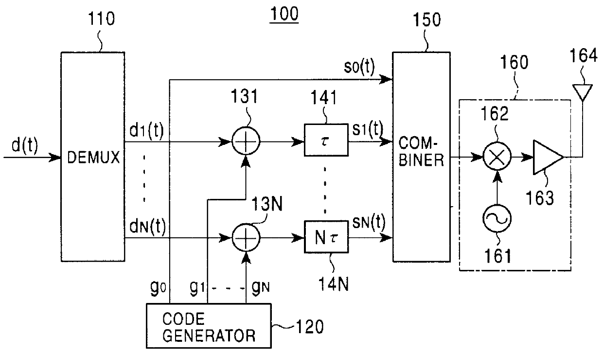
FIG. 1 illustrates the configuration of a transmitter (spread spectrum transmitter) 100 according to the first embodiment, which is installed both in a base station and in a mobile station.

Referring specifically to FIG. 1, the transmitter 100 comprises a demultiplexer (DEMUX) 110, a code generator 120 for parallelly generating N types of spread codes g1-gN, a N number of spreaders 131-13N, a N number of delay units 141-14N having different delay times in increments of a predetermined time .tau., a combiner 150, and an RF (radio frequency band) transmission unit 160. The RF transmission unit 160 in ...

second embodiment

(B) Second Embodiment

Next, a spread spectrum transmitter, a spread spectrum receiver and a spread spectrum communications system according to a second embodiment of the present invention will be described in detail while referring to the accompanying drawings. The second embodiment is also intended to apply the present invention to a CDMA mobile communications system.

FIG. 4 illustrates the configuration of a transmitter (spread spectrum transmitter) 100A according to the second embodiment, which is installed both in a base station and in a mobile station. It should be noted that in FIG. 4, parts identical or corresponding to those in the aforementioned transmitter 100 of the first embodiment illustrated in FIG. 1 are designated with the same reference numerals.

As is apparent from a comparison between FIG. 4 and FIG. 1, the transmitter 100A of the second embodiment further comprises a reference signal adder 170 between the combiner 150 and the RF transmission unit 160, in addition to...

third embodiment

(C) Third Embodiment

FIG. 5 illustrates the configuration of a transmitter (spread spectrum transmitter) 100B according to a third embodiment, which is installed both in a base station and in a mobile station. It should be noted that in FIG. 5, parts identical or corresponding to those in the aforementioned transmitter 100 of the first embodiment illustrated in FIG. 1 are designated with the same reference numerals.

In the first embodiment, the reference channel signal s0(t) is formed only of the reference spread code sequence go, whereas in the third embodiment, a signal generated by spreading reference data d0(t) with a reference spread code sequence g0 in a spreader 130 is used as a reference channel signal s0(t). The remaining aspects of the third embodiment are similar to the first embodiment, so that explanation thereof is omitted. In addition, the configuration of the receiver illustrated in FIG. 2 may be applied to the third embodiment.

The third embodiment can also have an adv...


PUM


Abstract

A spread spectrum communications system is provided for reducing the number of required matched filters to simplify the configuration associated with the reception. In a spread spectrum transmitter, a plurality of spread channel signals are synthesized by shifting their respective phases by a time sufficiently shorter than one symbol period. In a spread spectrum receiver, a plurality of spread code sequences are set one by one at a tap of a single matched filter in one symbol period in a time division manner to recover transmitted data.

Description

1. Field of the InventionThe present invention relates to spread spectrum communications systems, in particular, to spread spectrum transmitters and spread spectrum receivers which can be applied to mobile communications systems in accordance with a code division multiple access (CDMA) communications scheme for transmitting data, for example, having a transmission rate higher than that of one code channel using a plurality of codes.2. Description of the Related ArtReference is first made to the following documents related to the present invention:(1) U.S. Pat. No. 5,166,951; and(2) "Application Techniques for Spread Spectrum Communications Scheme" pp. 32-33 and pp. 53-59, published by Triceps Co., on Aug. 31, 1992.The spread spectrum communications scheme utilizes spread codes such as pseudo random codes or the like to spread transmission data over a wider bandwidth than an original data bandwidth for transmission. Since the spread spectrum communications scheme has a variety of fea...

Claims


Application Information

Patent Timeline
IPC IPC(8): H04B1/707H04J13/00H04B1/04H04B7/24H04W88/02
CPCH04B1/707
Inventor SHIINO, HARUHIRO
Owner CANON KK
Why Eureka
Try Eureka