Chair with calf support

Inactive Publication Date: 2001-01-02
PEGASUS
View PDF17 Cites 24 Cited by
  • Summary
  • Abstract
  • Description
  • Claims
  • Application Information

AI Technical Summary

Benefits of technology

The cushion members preferably have a sufficient width, transverse to the forward direction, to accommodate both legs of the person in the chair. The

Problems solved by technology

They are used for patients who are inactive or not sufficiently active to turn themselves regularly in bed, and who therefore run the risk of bed sores.
Because of t

Method used


Image

  • Chair with calf support
  • Chair with calf support
  • Chair with calf support

Examples


Embodiment Construction

An embodiment of the present invention will now be described by way of example, with reference to the accompanying drawings in which:

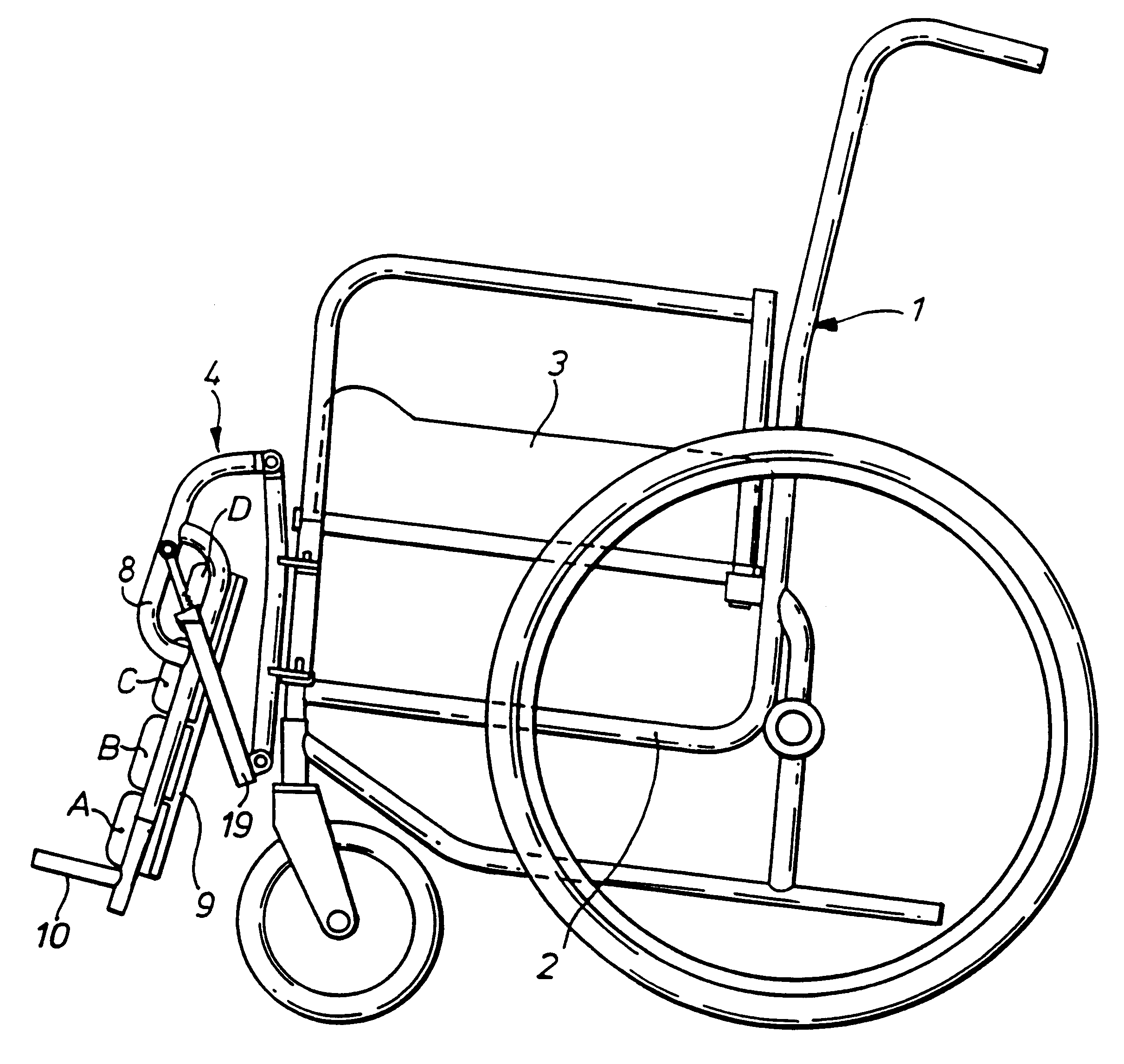
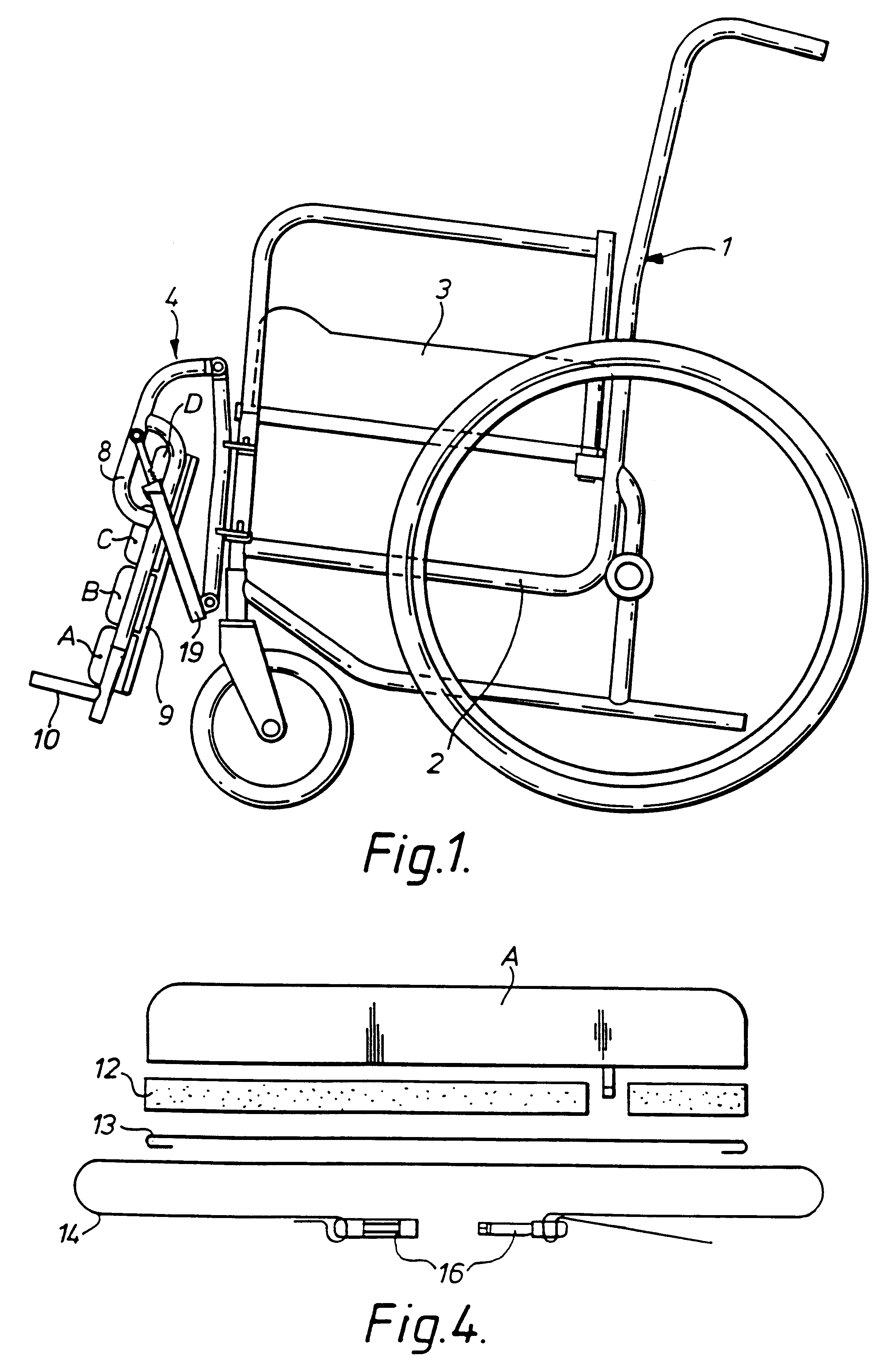
FIG. 1 is a side view of a wheelchair embodying the invention;

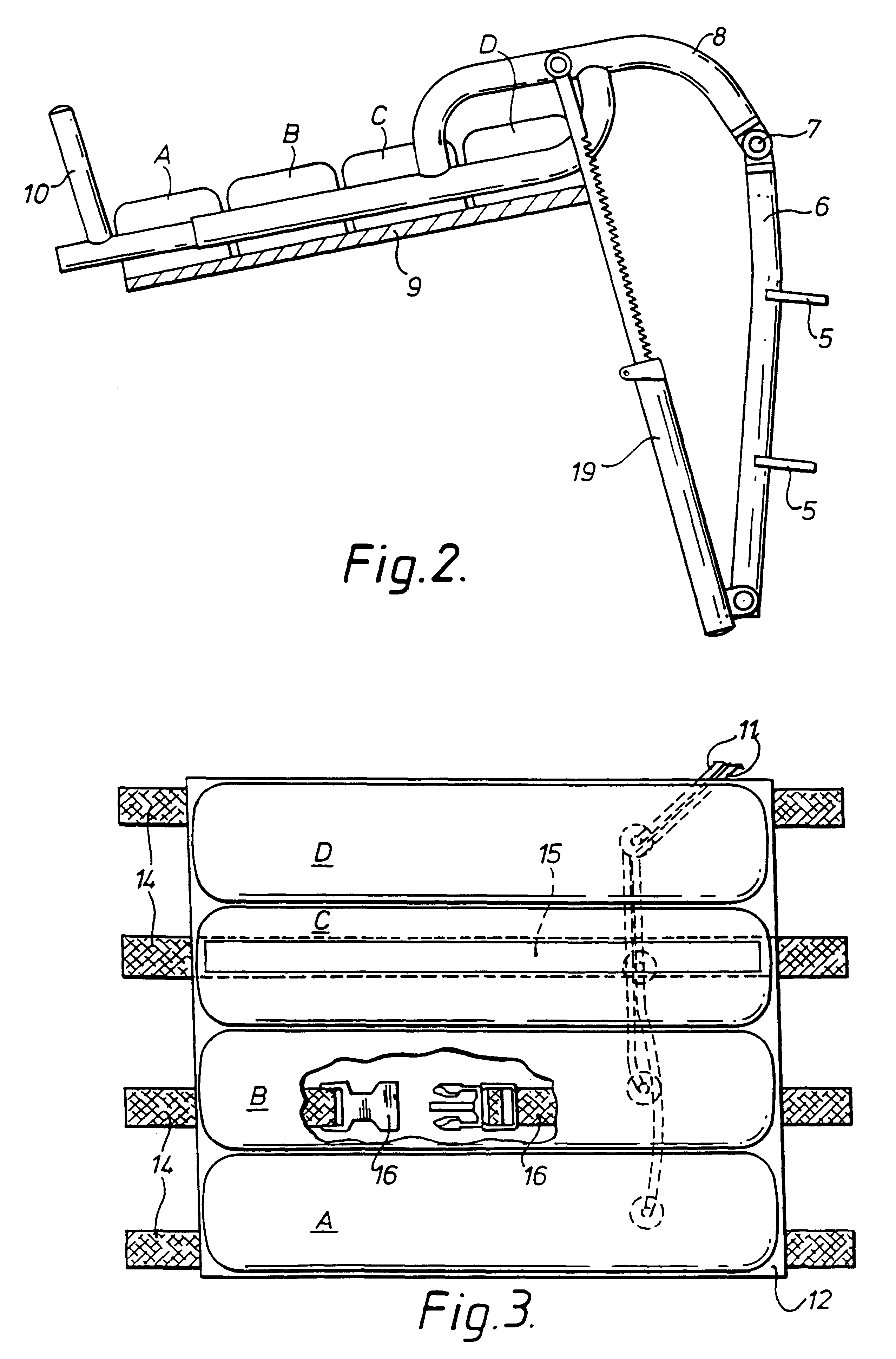
FIG. 2 is a side view of the calf support attachment of the wheelchair of FIG. 1, shown in its use position;

FIG. 3 is a plan view of the calf support portion of the attachment of FIG. 2; and

FIG. 4 is an explanatory diagram, corresponding to a transverse section of the support construction of FIG. 3.

FIG. 1 shows a wheelchair 1 which has a conventional frame structure 2 and has a seat 3 whose sitting surface is provided by a plurality of inflatable tubes aligned in the front to back direction of the chair. Under the seat is mounted a control system and a pressurised air supply system (not shown). Reference should be made to our co-pending application WO94 / 07396 for a full description of this seat and the control and inflation system. The system includes its own power supply in the form of one ...


PUM


Abstract

A chair, particularly a wheelchair (1), has a detachable active calf support (4), which has a plurality of inflatable cushion members (A, B, C, D) providing a calf support surface for a person in the chair. The cushion members are parallel transverse tubes forming an array extending away from the chair seat (3). The chair has a control for inflating and deflating the tubes in a predetermined sequence.

Description

This invention relates to chairs, especially wheelchairs, and to attachments for such chairs.BACKGROUND TO AND SUMMARY OF THE INVENTIONIn essence, the present invention provides an active calf support, for a person sitting in a chair, i.e. a support which applies a pressure varying with time to regions of the calf, for stimulation of venous return in the lower limb. The applicants believe that such an active calf support has not previously been proposed.Beds having a plurality of cushion members, e.g. transverse tubes, which are sequentially inflatable, are today well known. They are used for patients who are inactive or not sufficiently active to turn themselves regularly in bed, and who therefore run the risk of bed sores. The sequential inflation of the cushion members applies intermittent pressure to the skin, thereby reducing or preventing the formation of bed sores. An example of such a bed is the present applicants' GB-A-1595417. The present applicants have also sold active s...

Claims


Application Information

Patent Timeline
IPC IPC(8): A47C7/50A47C7/00A61G5/00A61G7/057A61G5/12A61G5/10
CPCA61G5/12A61G7/05776A61G2005/1045A61G2005/1054A61G2005/125A61G2005/127A61G2005/128Y10S297/03Y10S297/04A61G5/1054A61G5/1045A61G5/125A61G5/127A61G5/128
Inventor HANNAGAN, ANGUS PATRICK DOUGLAS
Owner PEGASUS
Why Eureka
Try Eureka