Indicator device

a technology of indicator device and plate, which is applied in the field of indicator device, can solve the problems of affecting the retail price of the plate, deteriorating the strip, and affecting the overall aesthetic appearance of the plate, and achieves the effect of reducing the production cos

Inactive Publication Date: 2001-01-09
TREU MASSIMO
View PDF2 Cites 12 Cited by
  • Summary
  • Abstract
  • Description
  • Claims
  • Application Information

AI Technical Summary

Benefits of technology

is to provide an indicator device which can be manufactured with any type of support material at a considerably lower production cost than the conventional methods, so as to induce purchasers to buy and use the device even where it is not expressly required.
Another object of the invention is to provide an indicator device which is resistant to abrasion and rubbing-induced wear and has a pleasant appearance.

Problems solved by technology

This solution is effective in itself, but it has the drawback that the strips deteriorate in the medium-long term, due to repeated contact, and degrade the overall aesthetic appearance of the plate.
A first drawback of this method is the fact that a specific mold must be provided for each plate, and if the plate is produced in a limited number of items this aspect considerably affects the retail price of the plate.
A second equally important drawback is that this method is difficult to use with metals and metallic alloys such as for example aluminum, copper and zinc-aluminum-magnesium alloys and entails considerably high production costs.

Method used


Image

  • Indicator device
  • Indicator device

Examples


Embodiment Construction

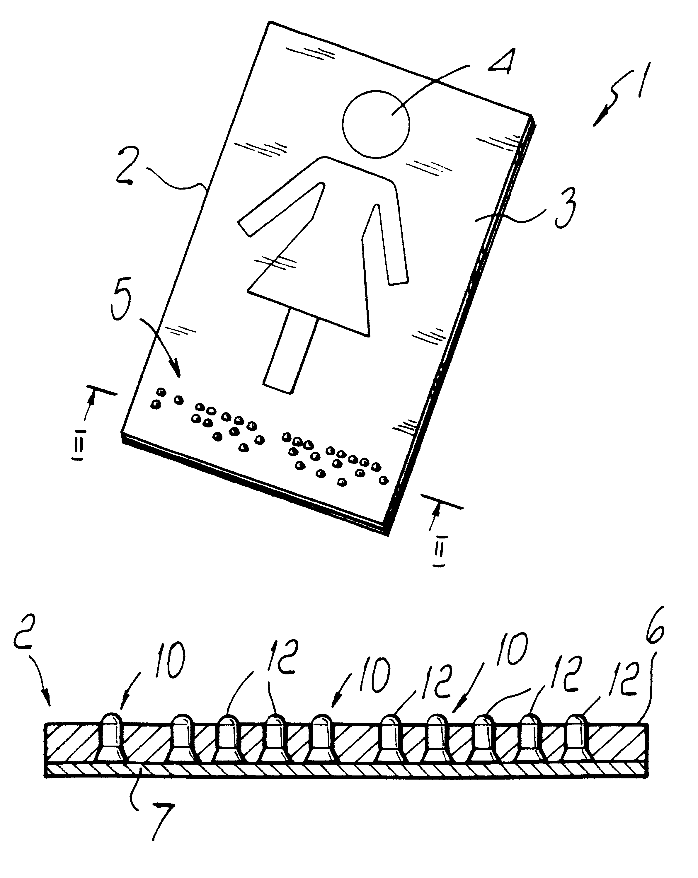
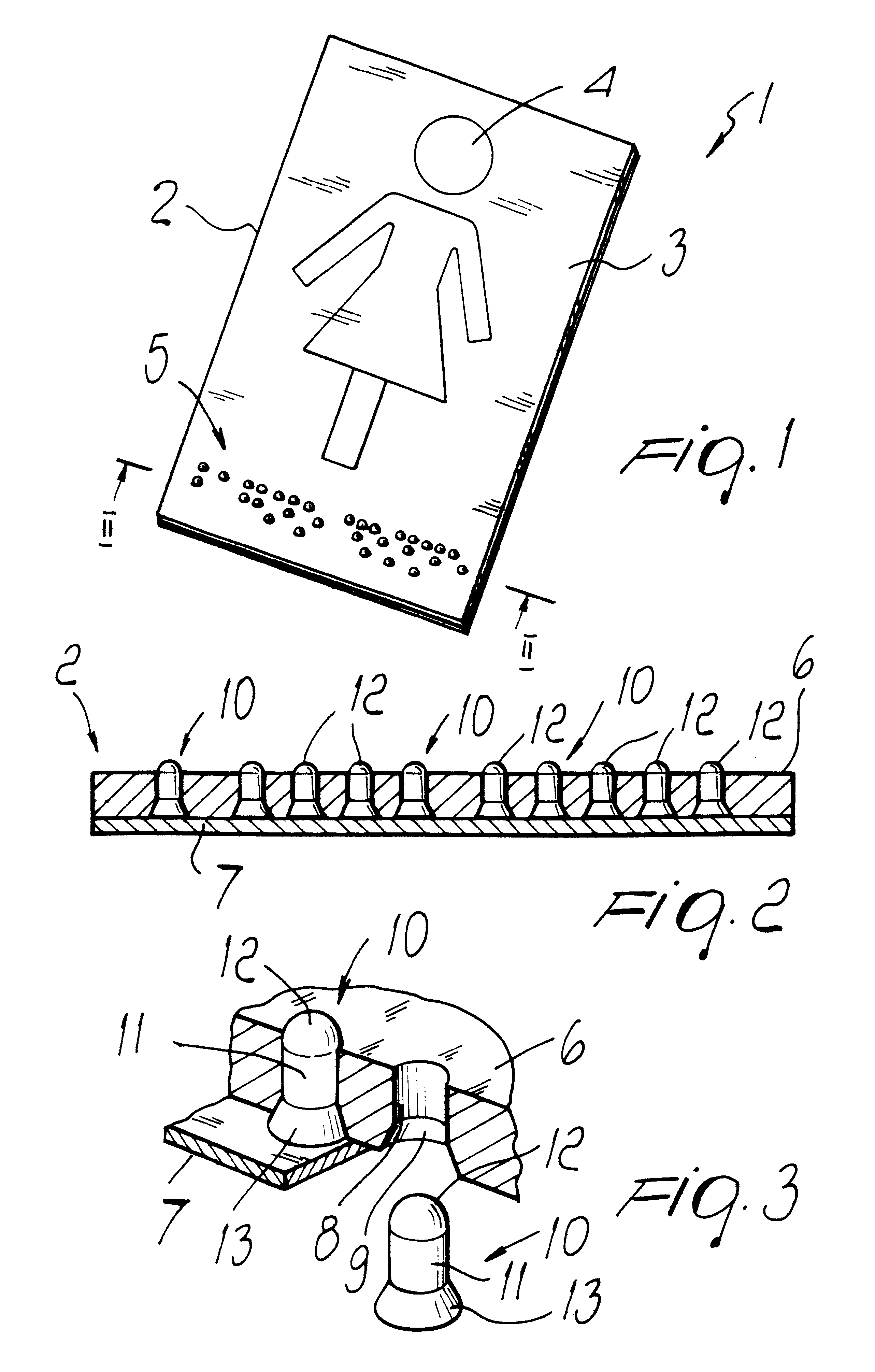
With reference to the drawings, the indicator device, globally designated by the reference numeral 1, comprises a support member 2 having a visible face 3 and provided with a conventional indication 4, for example provided by printing engraving, by means of an adhesive image, or in relief. The visible face 3 is also provided with an indication for visually-impaired and blind people, generally designated by the reference numeral 5, formed in Braille. The support member 2 comprises an upper exposed flat panel 6, preferably a metal or synthetic plate with desired characteristics in terms of rigidity and dimensional stability, which is coupled, by means for example of an adhesive, to a lower flat closure panel 7 which is optionally thinner than the upper panel 6, since it merely serves to close the upper panel. A plurality of through holes 8, that follow the pattern of Braille writing according to the alphanumeric characters to be represented are provided in the upper panel 6. Holes 8 h...


PUM


Abstract

An indicator device includes a support member formed by two coupled flat panels made of metal or synthetic material, a plurality of holes formed in the exposed panel according to the pattern of Braille writing according to the characters to be represented; the holes are engaged by pins made of synthetic material which is resistant to abrasion and to rubbing-induced wear, so that their dome-shaped rounded ends protrude from the exposed panel.

Description

1. Field of the InventionThe present invention relates to an indicator device which is particularly but not exclusively useful for visually-impaired and blind people in order to allow them to easily identify a place, an office, a direction et cetera.2. Description of the Prior ArtIt is known that the Braille system allows blind people to read by means of an array of raised dots which symbolize alphanumeric characters. Essentially, each letter and digit is written by mechanical punching on paper or other medium at some of the nodes of a two-by-three grid. Accordingly, by composing one or more grids which are punched in a horizontal direction one obtains words, etc. Reading is achieved by gently running one's fingertips along the resulting lines. This writing and reading system can also be applied to so-called place indicators in general and particularly to indicators of public bureaux, historical locations, hospitals and places of interest so as to enable blind people to autonomously...

Claims


Application Information

Patent Timeline
Patent Type & Authority Patents(United States)
IPC IPC(8): G09B21/00
CPCG09B21/003
Inventor TREU, MASSIMO
Owner TREU MASSIMO
Why Eureka
Try Eureka