
Panel for absorbing acoustic energy

Inactive Publication Date: 2001-01-09
SOUNDCOAT
View PDF3 Cites 4 Cited by
  • Summary
  • Abstract
  • Description
  • Claims
  • Application Information

AI Technical Summary

Benefits of technology

The acoustic absorbers provided in accordance with the present invention satisfy long felt needs in the art for efficient absorption of acoustic driving forces to protect payloads and fairings before and during launch. These absorbers also completely protect payloads from contaminant particles which may escape from the acoustic absorbing foams which comprise the panels, and are themselves protected from deleterious contaminants in the atmosphere of the fairings and from solvents the absorbers may come into contact with during storage or handling. Additionally by judicious choice of panel components in accordance with the present invention, contamination of the atmosphere is reduced and the growth of common funguses which occurs in prior sound absorbing panels during storage is markedly decreased. Certain subcomponents of the panels and acoustic absorbers of the present invention are constructed in accordance with military standards which require the highest degree of cleanliness and product integrity. In particular, these subcomponents of the sound absorbing panels described and claimed herein meet or exceed the requirements of MIL-STD-1246C (Apr. 11, 1994), the teachings of which are expressly incorporated herein by reference. It will be recognized by those skilled in the art that the panels of the present invention may be constructed in accordance with other common standards such as those available from the National Aeronautics and Space Administration (NASA) and the American Society for the Testing of Materials (ASTM), for example.
Furthermore with the efficient use of a vent system, the panels do not expand due to differential pressures during launch, thereby protecting the payload during launch. Since the absorbers of the present invention do not require any complicated structures, they are economical to fabricate, and simple to mount to a surface of the fairing. Such results have not heretofore been achieved in the art.

Problems solved by technology

Fairings and payloads are typically mounted to the top of the rocket and are thus subjected to severe forces.
Aerodynamic, heat, and acoustic forces all combine to produce a stressful and mechanically challenging environment for the satellite within the fairing.
Such intense acoustic loads can damage the satellite within the fairing and contribute to the degradation of performance of satellite subsystems such as solar cells, control systems, and communication systems.
One of the major problems with these types of foams however is that they tend to emit particles into the atmosphere of the fairing which contaminate the atmosphere and can settle on portions of the payload, thereby damaging or impeding the performance of the payload during launch and later on in orbit.
However, the thin protective foil is not placed around the entire absorbing foam in the Borchers et al. patent and the sides of the panel which are not covered by the foil must be adhered to the fairing surfaces directly which allows for outgassing from the foam to occur and for the panel to become easily detached from the fairing wall which is threatening to the payload.
The sound absorbing panels of the Borchers et al. patent require complicated structures to be formed out of the polyimide material.
Furthermore, since the thin protective foil which covers one side of the panels of Borchers et al. does not encompass the entire foam structure, there still remains the dangerous possibility of a leak of contaminants into the fairing's atmosphere and vice-versa.
Additionally, the use of fine perforations in the protective foil will also allow gases to escape into the fairing atmosphere and does not provide for adequate differential pressure compensation and further increases the possibility of contaminating the fairing's atmosphere with the foamed material.
This way of securing acoustic absorbing panels to the fairing is inefficient and dangerous since during liftoff the panels can become disengaged from the fairing surface due to the severe forces that are generated.
Additionally, the use of mechanical fasteners greatly increases installation time and is therefore also economically inefficient.
Further, the mechanical fasteners undesirably increase the weight of the acoustic absorbing panels.
Thus, prior mechanical fastening of acoustic panels to fairings is not safe, economical or effective.

Method used


Image

  • Panel for absorbing acoustic energy
  • Panel for absorbing acoustic energy
  • Panel for absorbing acoustic energy

Examples


Embodiment Construction

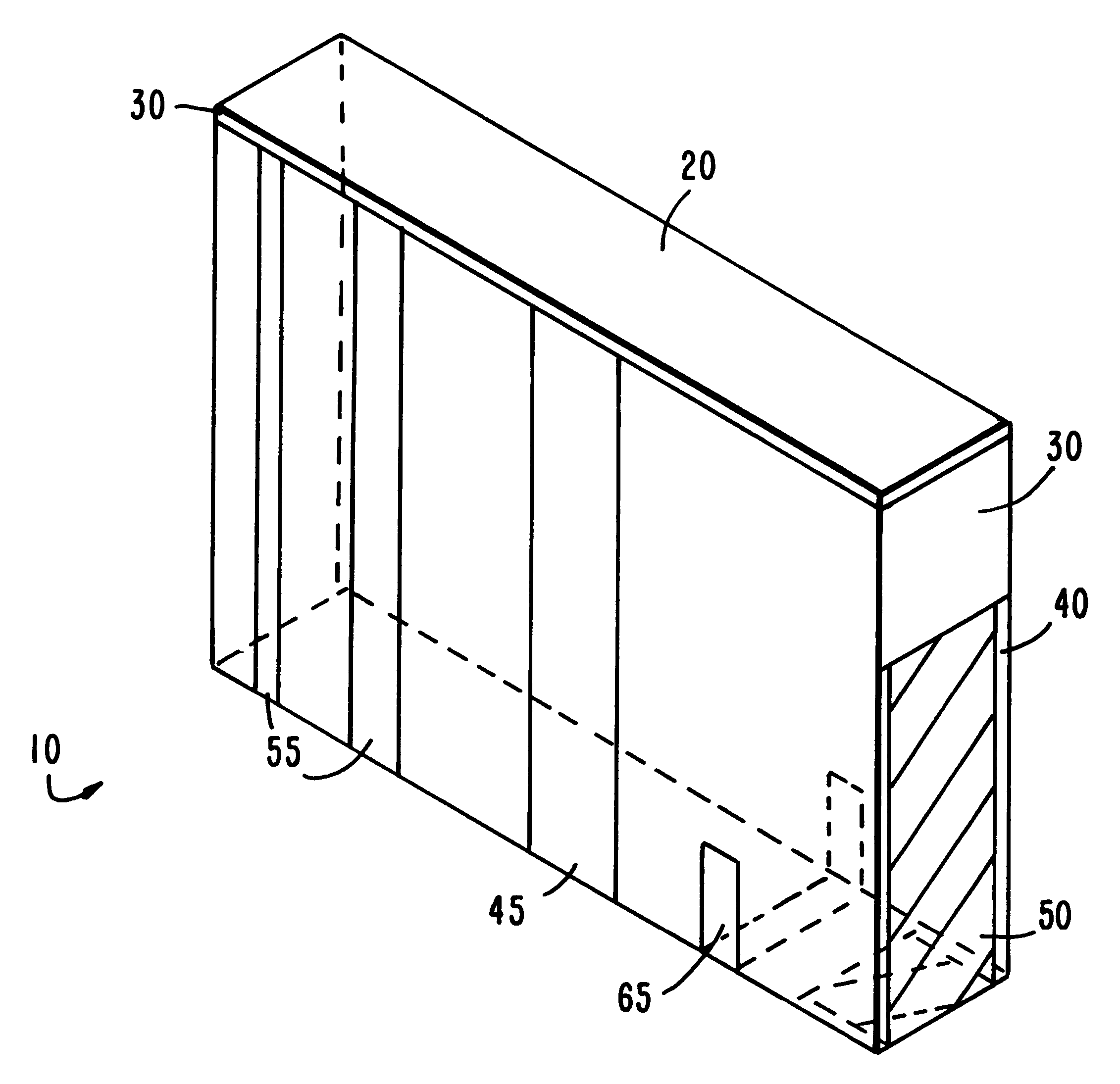
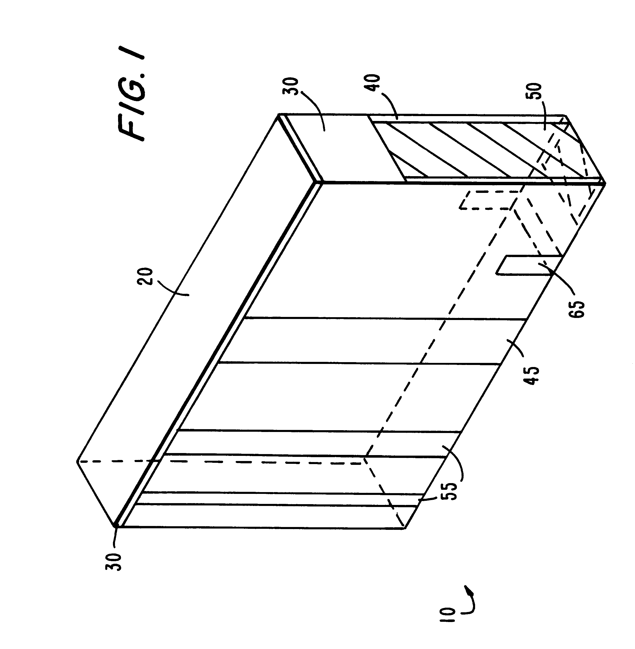
Referring now to the drawings, in FIG. 1 a lightweight acoustic absorbing panel is shown generally at 10. The absorbing panels of the present invention are particularly useful for absorbing acoustical energy created during a launch of a rocket. As used herein, the term "launch" denotes the period of time beginning with the ignition of the rocket carrying the fairing and payload, during liftoff and ascent of the rocket, through the time when the fairing and payload finally separate from the rocket. The acoustic absorbing panels 10 also protect the payload within the fairing before launch from contamination and electrostatic discharge (ESD) which may occur as various electrical systems of the payload and the rocket are used and tested, for example. In particular, the panels described herein advantageously line the inside surface of a fairing containing a vehicle, payload or satellite, as the terms are used interchangeably herein, which is susceptible to damage from acoustic vibration....


PUM


Abstract

Lightweight acoustic absorbers. The acoustic absorbers absorb energy during launch of a vehicle by a rocket, and are adapted to line the inside of a cavity of a fairing containing a vehicle. The absorbers comprise acoustic absorbing members, and a layer substantially surrounding the acoustic absorbing member which is substantially impermeable to contaminating particulates found within the fairing, and substantially impermeable to any contaminants which may be emitted by the acoustic absorbing member. A plurality of vents are cut in the layer, and a filter is placed over the vents to filter out any contaminants. The vents allow the gases within the fairing and the acoustic absorbing member to pass therethrough, thereby compensating for differential pressure.

Description

1. Field of the InventionThis invention relates generally to acoustic absorbers. More particularly, this invention relates to lightweight acoustic absorbers that absorb energy during launch of a vehicle by a rocket, and which generally prevent contamination of a fairing containing the vehicle.2. Description of the Related ArtSince the beginning of the United States Space Program in the '60s, payloads such as satellites have been lifted by expendable and non-expendable launch vehicles into orbit and beyond. Typically, a payload fairing is provided to house the vehicle or satellite and to prevent damage to the vehicles therein before and after launch. Fairings have been used extensively in the payload lifting art, and will be continued to be used as this art progresses to more sophisticated land based launches and the new expected sea launch of space vehicles and payloads.Fairings and payloads are typically mounted to the top of the rocket and are thus subjected to severe forces. Aero...

Claims


Application Information

Patent Timeline
IPC IPC(8): B64G1/22B64G1/52G10K11/16G10K11/00G10K11/162B64G1/00
CPCB64G1/52G10K11/16G10K11/162B64G1/002B64G2001/228B64G1/228
Inventor RAO, DATTATRAYKOCH, JOHNVO, BAOSIMPSON, CLAY
Owner SOUNDCOAT
Learn More