Molding fastener products having backings

a technology of backings and fasteners, which is applied in the direction of weaving, transportation and packaging, and other domestic objects, can solve the problems of loss of convenience advantage, limited seaming, and limited material nature of seams

Inactive Publication Date: 2001-01-16
VELCRO IND BV
View PDF36 Cites 75 Cited by
  • Summary
  • Abstract
  • Description
  • Claims
  • Application Information

AI Technical Summary

Benefits of technology

The process described in U.S. Pat. No. 4,794,028 for making plastic hooks utilizes an apparatus described in U.S. Pat. No. 4,775,310 comprising "a first cooled unitary forming roller having a plurality of hook forming cavities defined in the periphery thereof and extending inwardly therefrom; a second pressure roller positioned for coaction with said first forming roller; means for concurrently rotating said first and second rollers in opposite directions about their generally respective axis; means for forming a striplike extrusion of molten plastic material adjacent said first and second rollers to be directed therebetween at an interface thereof such that said plastic material fills said hook forming cavities and forms a striplike member having a base portion and a great multiplicity of hooklike projections extending from one surface of said base portion and integral therewith; means for removing said striplike member from said first forming roller at a position spaced from the interface of said first and second rollers such that said hooklike projections are withdrawn from said hook forming cavities without opening said cavities after being cooled by the first forming roller to a desired temperature." I have found it possible to introduce into the nip, formed by the two cylinders, various sheet materials which will become an integral part of the striplike material on the side opposite the hooks. Surprisingly, introduction of such materials into the nip along with the molten plastic does not interfere with the operation of the process and while certain cautions and limitations are, of course, desirable, the formation of such insitu laminates proceeds to great advantage. I have found a very wide variety of materials, such as nonwoven fabrics, woven and knitted textiles, reinforcing yarns, scrims and nettings, sheets of paper, plastic films, metallic window screening and almost any material in filmlike or thin sheet form can be handled in this manner. The formation of the striplike plastic fastener sheet insitu with a porous foreign backing most often is accomplished by infusion of the molten plastic into the structure of the web material where there is an intimate intermingling of the plastic within the pores of the web. In the case of nonporous films, the films tend to melt on their surface forming an intermolecular diffusion which forms a strong bond between the sheets. The inclusion of such foreign materials provides a substantial advantage over prior art methods of creating laminates. Such striplike materials contain no foreign material; the bonds are strong and a wide range of materials may be joined in this way. Additionally, the process of adding the backing at the time of creating the hooks offers economic advantages over the more conventional processes of creating a laminate using adhesives or other bonding agents in second stage processes.

Problems solved by technology

Sewing, however, is limited as to the nature of the material to which the fastener may be attached.
Such difficulties present particular problems for hook and loop fasteners.
This class of products are convenience products and if it is necessary to apply complex chemical treatments to the tape prior to bonding the convenience advantage is lost.
It is known to apply pressure sensitive adhesives to such fasteners by the application of corona treatments in the manufacturing facilities where the fastener tapes are manufactured but such treatments are not available for many users and do not present a reasonable solution for creating a fastener surface which is readily bondable to a wide variety of surfaces using a wide range of adhesive types.
The backing of U.S. Pat. No. 3,594,865 is primarily a support onto which hooks are formed and does not modify the backing of the fastener to receive adhesives or gluing agents nor is it possible to utilize loop materials as the backing material to form back to back fasteners.
It is also known to use complex laminating methods to add a bondable surface to many sheet materials but such methods are expensive and often create a final product which has undesirable characteristics such as bulk, stiffness, a tendency to delaminate, operating temperature limitations or other properties making the laminate undesirable.
The limitation of such products in the past has focused on the method used to laminate the two components together as described above.
The bulk created by the adhesive bonding of such laminates has clearly limited its usefulness.

Method used


Image

  • Molding fastener products having backings
  • Molding fastener products having backings
  • Molding fastener products having backings

Examples


example ii

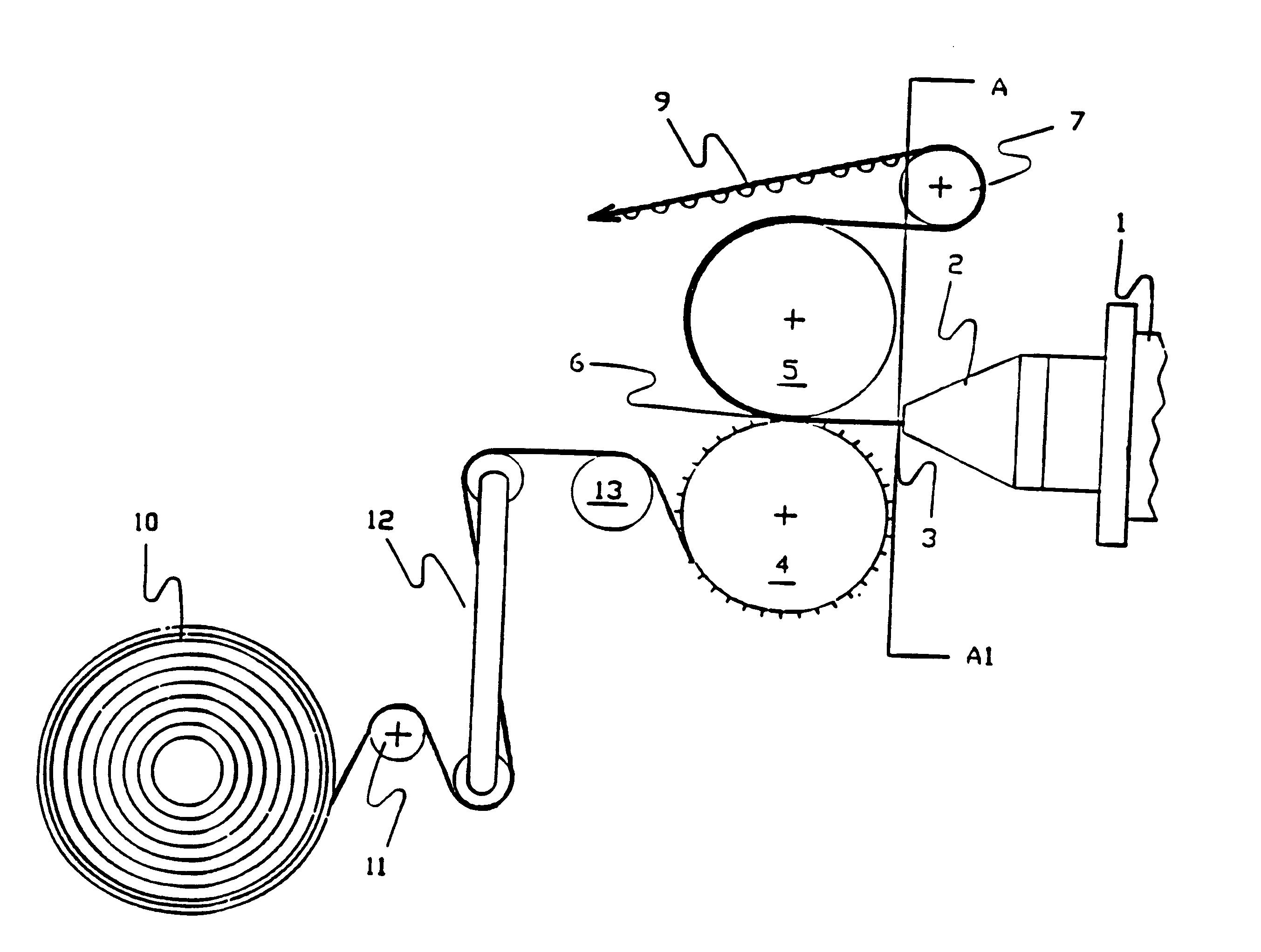
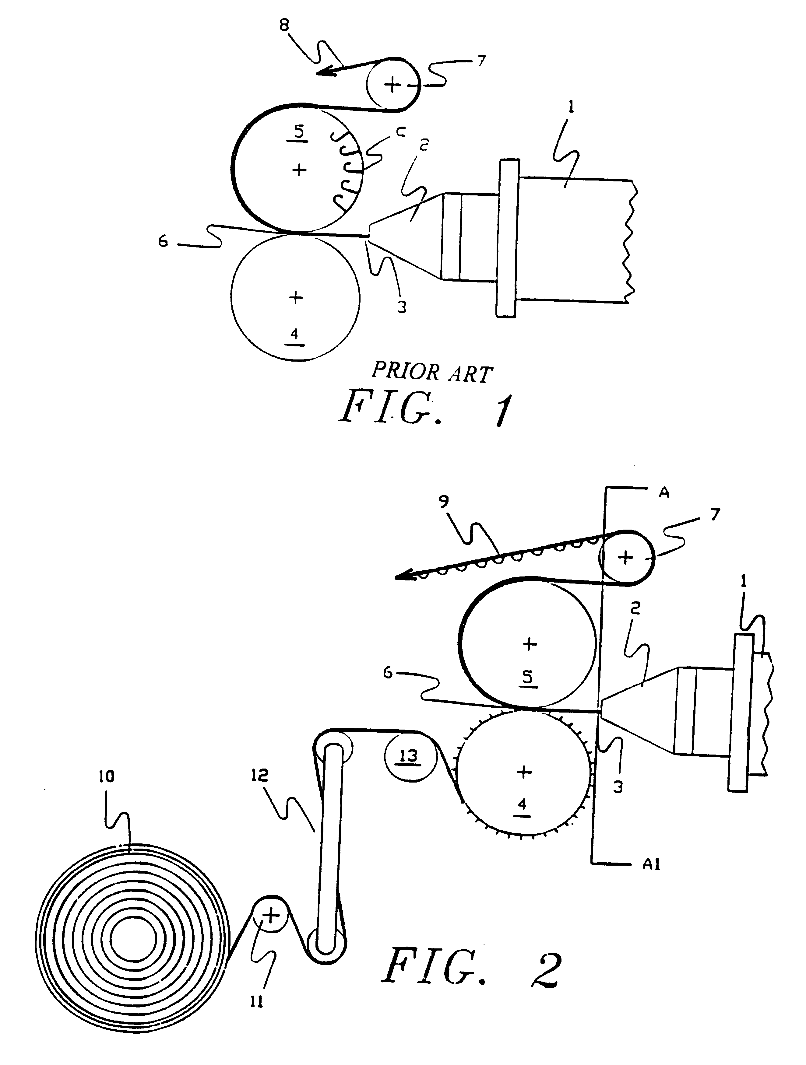
The apparatus described in U.S. Pat. No. 4,775,310 was set up to produce a plastic hook product designated as hook type CEM-15 by the Velcro Group Corporation, using a co-polyester resin sold by the DuPont Company, a Hytrel.sup.R 8238 with 10% of a master batch fire retardant added to provide fire resistance to the final product. The melt temperature of the polymer, at the end of the extruder, was 475.degree. F. and the die temperature was 476.degree. F. The line speed was 30 feet per minute. A roll of spunbonded nonwoven fabric, sold as Remay.sup.R 2016, weighing 1.35 ounces per square yard with a thickness of 0.009 inches was slit to 10 inches width and introduced into the nip formed by the bottom and forming rolls of the device as described in Example I. The bottom roll temperature was 50.degree. F., the forming roll temperature was 50.degree. F. and the top roll temperature was 90.degree. F. A tension of 100 pounds was exerted against the spun bonded fabric in order to prevent w...

example iii

Exactly the same configuration as used in Example II was utilized but the spunhonded nonwoven used was a lighter weight version of Remay, designated as Remary.sup.R style 2006, weighing 0.6 ounces per square yard with a thickness of 0.006 inches. In order to eliminate wrinkles and folds from the web, tension was reduced to 25 pounds and the same overfeed was used on the bottom roller. The product formed by this combination was similar to that of Example II but the mingling of the polymer into the interstices of the nonwoven was greater than in that example, but it was still possible to raise fibers from the surface by vigorous rubbing, and there were many fibers on the surface of the plastic projecting as a very fine fuzz above the surface.

example iv

Exactly the same configuration as used in Examples II and III were utilized but the spunbonded nonwoven used was even lighter then in the previous examples. The version of Remay in this example was designated as Remay.sup.R style 2250, weighing 0.5 ounces per square yard with a thickness of 0.004 inches. In order to eliminate wrinkles and folds from the web, tension was reduced to 20 pounds and the overfeed was increased to 9% on the bottom roller. The product formed by this combination was similar to those of Examples II and III but the mingling of the polymer into the interstices of the nonwoven was marginally greater than in Example III. This mingling was enhanced to the extent it was difficult to raise fibers from the surface by vigorous rubbing even when using a coin to abrade the surface. Yet it was possible to clearly see the fibers on the surface as an integral part of the surface and even projecting as a very fine fuzz from the surface.


PUM

PropertyMeasurementUnit
temperatureaaaaaaaaaa
widthaaaaaaaaaa

Abstract

An extruded hook fastener strip is created on a roll having hook forming cavities in its surface by extruding plastic material into the interface between the forming roll and a second strip carried by a backing roll. The second strip is firmly bonded to the fastener strip on that side opposite the formed hooks.

Description

This invention relates to an improved fastener of the hook and loop type and a method for producing the same using a combined extrusion / roll forming process. The assignee of this application is owner of U.S. Pat. No. 4,775,310 which describes an apparatus for making a separable fastener and U.S. Pat. No. 4,872,243 which describes the product produced by the apparatus of the former patent. Striplike fasteners of the type described in the subject patents comprise a great multiplicity of closely spaced upstanding hooklike projections to releasably engage loops of a companion fastener strip to form a cyclable or semipermanent closure sold in the trade under the brand name Velcro.sup.R. Depending upon the configuration of the multihook fastener, many different types of material are adapted for coaction therewith to effect joining of the structures to which the strip fasteners are themselves joined. Such fastener devices are finding broad usage in such diverse applications as securing aut...

Claims


Application Information

Patent Timeline
Patent Type & Authority Patents(United States)
IPC IPC(8): A44B18/00B29C43/22B29C59/02B29D5/00
CPCA44B18/0003A44B18/0049A44B18/0073A44B18/0084A44B18/0092B29C43/222B29C59/025B29D5/00B29C43/46A44B18/0007Y10T24/2708B29C2043/465B29L2031/729B29C2043/461Y10T24/2758Y10T428/24008Y10T24/2775Y10T24/27Y10T428/24017Y10T24/2733Y10T24/275Y10T24/2792Y10T442/184Y10T442/15Y10T442/155Y10T442/109Y10T442/164Y10T428/249958Y10T442/102Y10T428/249959B60N2/5833
Inventor KENNEDY, WILLIAM J.PROVOST, GEORGE A.ROCHA, GERALD F.
Owner VELCRO IND BV
Why Eureka
Try Eureka