
Spinal cord electrode assembly having laterally extending portions

a technology of spinal cord and electrode assembly, which is applied in the direction of spinal electrodes, internal electrodes, therapy, etc., can solve the problems of affecting the effect of the treatment, and causing the entire procedure to be suspect, so as to achieve the effect of avoiding recurrence and reducing the risk of recurren

Inactive Publication Date: 2001-01-16
ELECTRO CORE TECH
View PDF3 Cites 64 Cited by
  • Summary
  • Abstract
  • Description
  • Claims
  • Application Information

AI Technical Summary

Benefits of technology

Correspondingly, it is also an object of the present invention to provide a spinal cord stimulator assembly which permits attachment of the electrode to surrounding soft tissue while minimizing the risk of inadvertent damage to the electrical contacts and thin wire leads of the device.
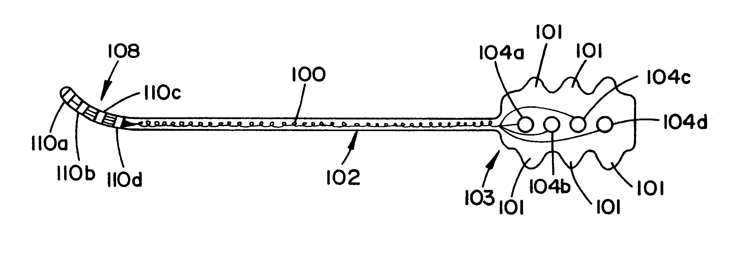
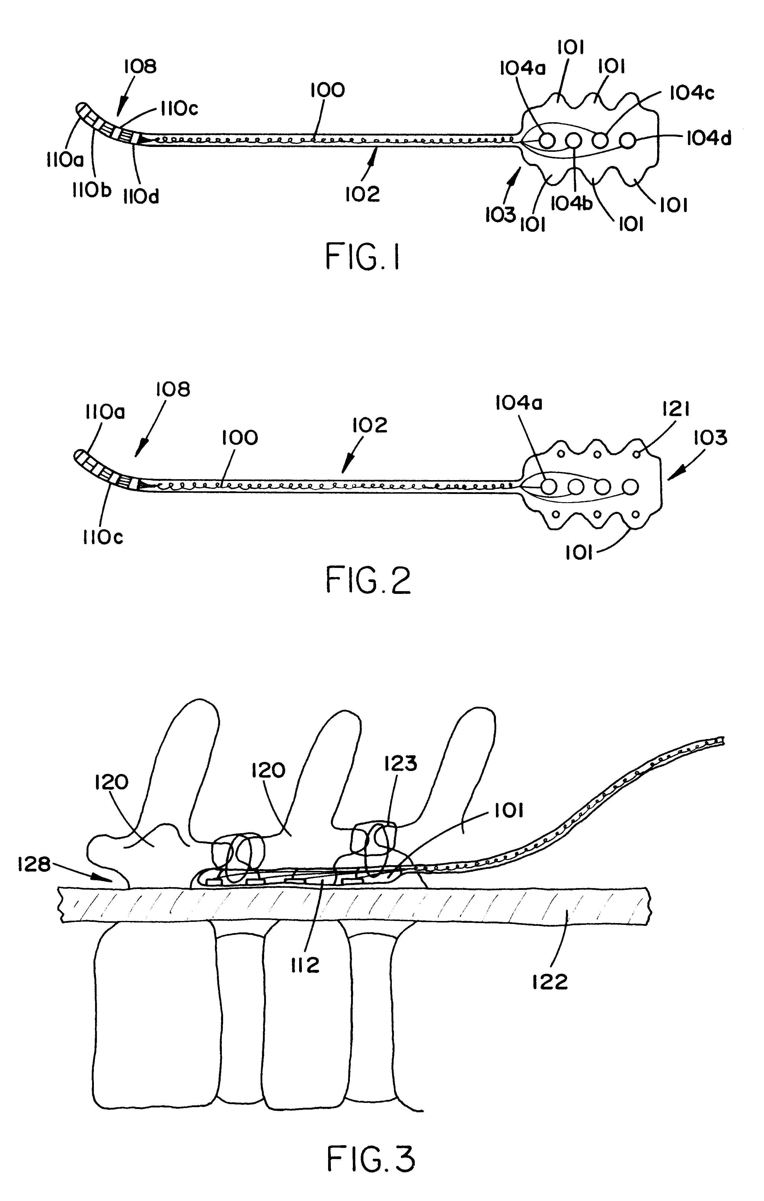
The preceding expressed object is provided in the present invention, which comprises new and novel embodiments of electrode and vertebral attachment devices for use in spinal cord stimulation, and which may be used in conjunction with standard and / or advanced electrical signal sources. More particularly, a variety of different embodiments of the present invention are contemplated, preferred ones of which are disclosed herein, including electrode assemblies having terminal pads which comprise laterally extending elastomeric material which does not include any electrically active materials, and which is ideal for receiving a suture, therethrough. These laterally extending suture receiving portions may further be color coded by the inclusion of a readily discernable dye by which the surgeon may easily recognize the safe portions of the terminal pad through which he may suture. These laterally extending suture pads may further (or alternatively) include small through holes which the surgeon may insert guidewires or other fastening devices for anchoring the electrode to surrounding bony tissue through which the surgeon would not otherwise be able to suture.
More particularly, the distal end of the electrode comprises a series of electrical terminals, generally equivalent in number to the number of electrical contacts at the proximal end (one terminal at the distal end and one electrical contact in the proximal end are preferably individually coupled to one another by one wire lead, each coupled set being in electrical isolation with the other sets so that each may carry a different potential). The terminals and the portion of the elastomeric sheath which contains them may be cylindrical (as is the rest of the sheath), however, it is preferred in the present invention that it be flattened out, forming a planar pad structure. The planar terminal pad generally includes a series of individual terminals which are generally circular and planar. As suggested above, the terminal pads are spaced apart from one another so that they are in at least partial electrical isolation from one another. The application of a voltage differential across the pads (by the coupling of the corresponding electrical contacts to different, or variable, voltage sources) causes a current to flow through the adjacent tissue. This current causes the disruption of pain signals in the target nerve roots, thus alleviating pain.
The terminal pad portion of the present invention, and specifically the new and novel features thereof, include means for attaching the pad to surrounding tissue. More particularly, in a first embodiment, the terminal pad includes at least one laterally extending portion which is formed of the same elastomeric material as the sheath in which the wire leads are encased. This at least one laterally extending portion preferably includes multiple symmetric laterally extending portions. These portions are provided so that the surgeon may suture the terminal pad to soft tissue matter which is adjacent to the desired target nerve site. In a first preferred variation of this embodiment, the laterally extending portions of the terminal pad, which is the portion through which the sutures are to be placed, includes a color coding which is visually distinct from the portion of the terminal pad which includes the electrical terminals (generally this portion is transparent--or at least a colorless translucent material). This distinct coloring provides the surgeon with a readily apparent target through which he or she can have a high level of confidence that the suture will not disrupt electrical signalling, or introduce a loss of integrity to the fluid barrier between the electrical components and the patient's fluids.

Problems solved by technology

In addition, the high frequencies of electrode migration from the target site or sites rendered the entire procedure suspect.
In addition, the leads would still easily become dislodged and migrate from the desired treatment site, usually becoming ineffective, but sometimes having actively negative effects on other nerves.
These limitations and failures associated with multiple implantations of single lead electrodes briefly caused a reversion to the older, more invasive approach.
Unfortunately, while eliminating some of the causes associated with electrode migration, and reducing the number of electrodes which could migrate, the advances did not address the fundamental inability to fix the electrode at the appropriate location.
Subsequent limited attempts to identify ways to stabilize the electrode at a specific location in the spine have been limited to integrating a fabric material into the terminal pad portion of the electrode, which fabric extends laterally out from the elastomeric pad portion, through which the surgeon may suture the electrode to the surrounding tissue.
Unfortunately, surgeons generally prefer to suture through the more substantial elastomeric material of the terminal pad, thereby risking damaging the electrical contacts and leads therein.

Method used


Image

  • Spinal cord electrode assembly having laterally extending portions
  • Spinal cord electrode assembly having laterally extending portions

Examples


Embodiment Construction

While the present invention will be described more fully hereinafter with reference to the accompanying drawings, in which particular embodiments are shown, and with respect to methods of implantation, it is to be understood at the outset that persons skilled in the art may modify the invention herein described while achieving the functions and results of this invention. Accordingly, the descriptions which follow are to be understood as illustrative and exemplary of specific structures, aspects and features within the broad scope of the present invention and not as limiting of such broad scope. Like numbers refer to similar features of like elements throughout.

Referring now to FIG. 1, the present invention comprises a spinal cord stimulation electrode having laterally extending portions 101 of the terminal pad section 103. The laterally extending portions 101 are provided so that the surgeon may have a structural portion through which he or she may safely introduce a suture to ancho...


PUM


Abstract

A spinal electrode for use in spinal cord stimulation having portions which are specifically provided for coupling the electrode to the adjacent spinal tissue so that displacement of the electrode cannot easily occur by normal bodily motion as is a failure mechanism of prior electrode designs. The distal end of the electrode which includes the electrical contacts also includes at least one laterally extending non-electrical portion. The extending portions are provided for receiving a suture or wire therethrough. The laterally extending portions may include a readily identifiable distinguishing feature, such as a color dye or a textural difference, so that it can be readily seen as a safe region through which a suture may be passed. Alternatively (or in addition), the laterally extending portions may include a through hole so that the tip of the electrode may be tied to the spinous process (or other spinal bone) by a wire.

Description

1. Field of the InventionThis invention relates generally to a device used in the treatment of neurological disorders, especially pain and motor dysfunction by electro-stimulation of the spinal cord, and more particularly to a novel electrode having integrally formed attachment means which permit more reliable positioning of the electrode relative to the spinal cord.2. Description of the Prior ArtThe use of electrical stimulation for the purposes of alleviating pain and the treatment of other neurological afflictions has been utilized for a number of years, and in many instances has become the standard of care. In new applications, as well, electrical stimulation of components of the nervous system continues to show significant therapeutic promise.More particularly, in the spine, the original approach to electrical stimulation was to place multiple electrical leads directly onto the dura around the spinal cord. In such a procedure, the larninae of a sequence of vertebrae were remove...

Claims


Application Information

Patent Timeline
IPC IPC(8): A61N1/05
CPCA61N1/0551
Inventor ERRICO, JOSEPH P.ERRICO, THOMAS J.
Owner ELECTRO CORE TECH
Learn More