Method of reducing distortion in a spray formed rapid tool

Inactive Publication Date: 2001-01-30
FORD GLOBAL TECH LLC
View PDF22 Cites 14 Cited by
  • Summary
  • Abstract
  • Description
  • Claims
  • Application Information

AI Technical Summary

Problems solved by technology

This can result in distortion of the spray formed rapid tool as shrinkage of the sprayed metal occurs.
Although the above process for making a spray formed rapid tool has worked well, it suffers from the disadvantage that trial spray runs have to be conducted to determine the spray parameters for spraying the spray formed rapid tool.
Another disadvantage of the above process is that the spray

Method used


Image

  • Method of reducing distortion in a spray formed rapid tool
  • Method of reducing distortion in a spray formed rapid tool
  • Method of reducing distortion in a spray formed rapid tool

Examples


Embodiment Construction

)

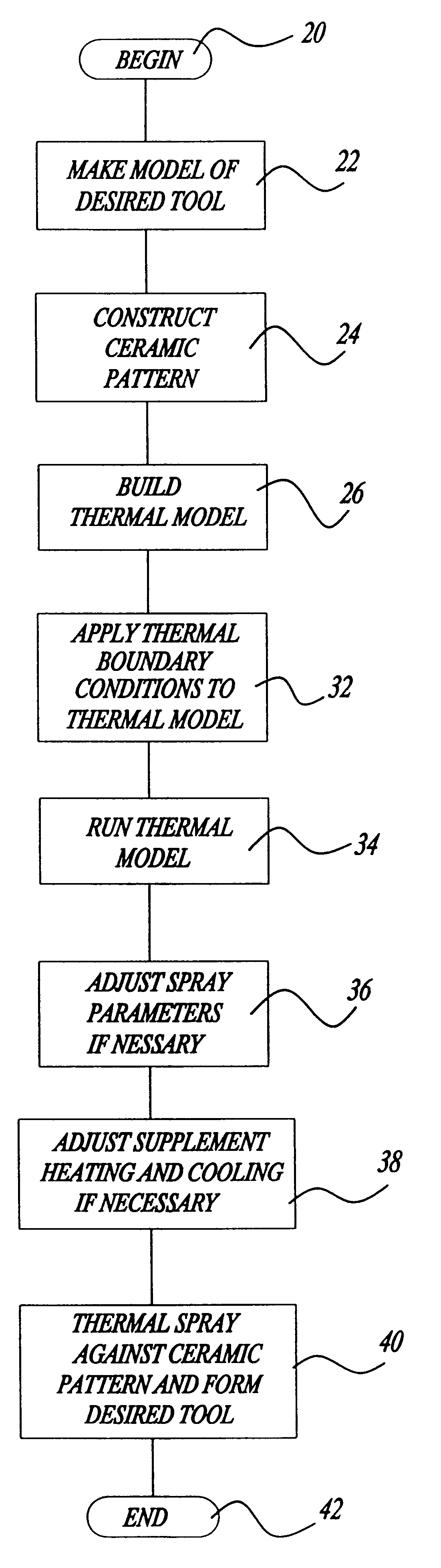
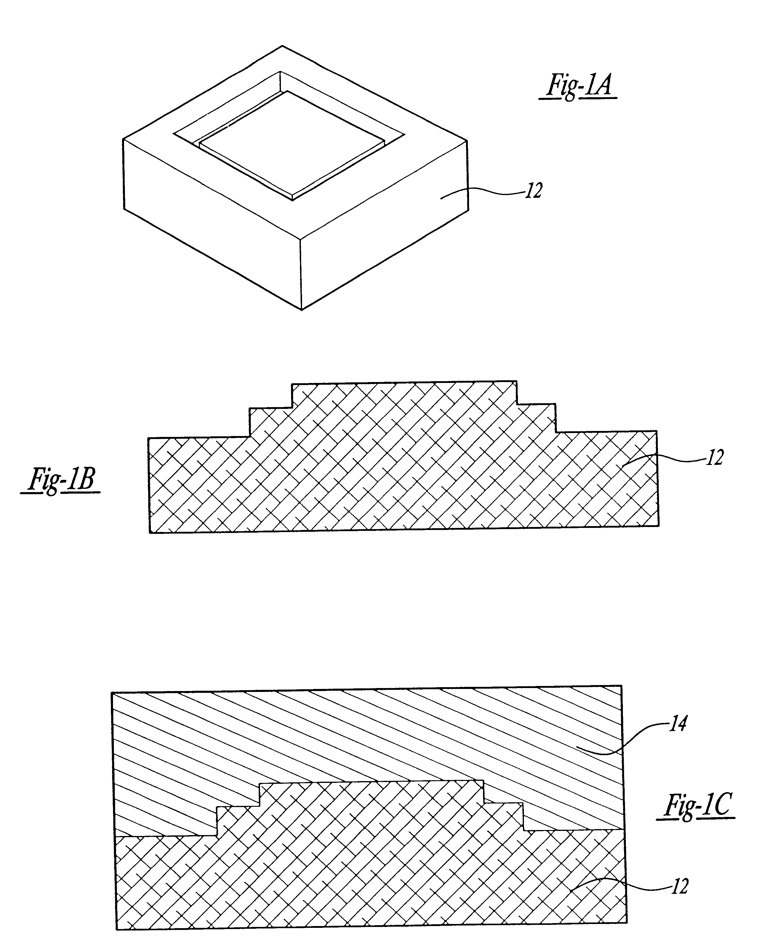
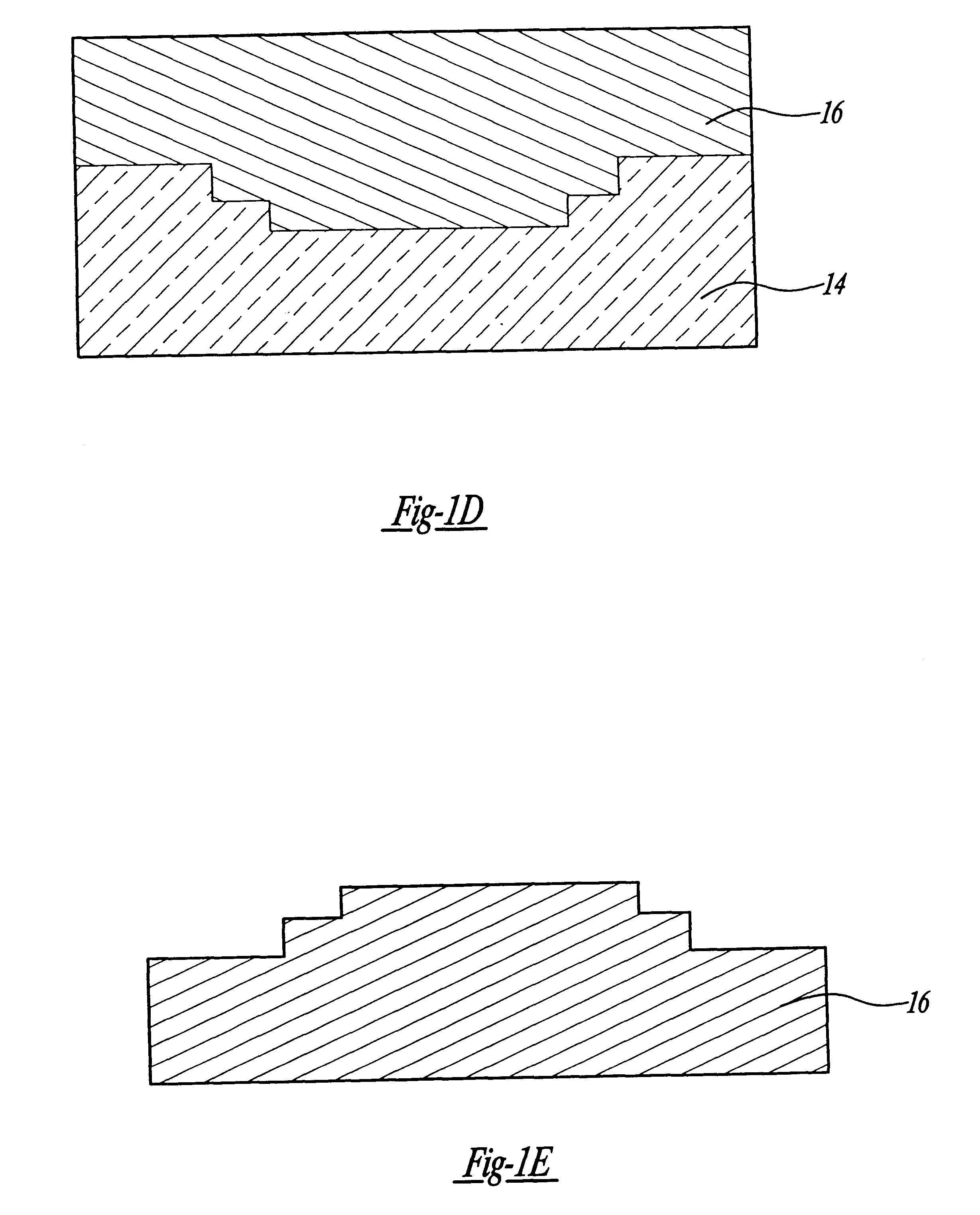
Referring to the drawings and in particular FIGS. 1A through 1E, one embodiment of a method of forming a spray formed rapid tool is shown. The method begins by creating or making a master model 12 of a desired tool as illustrated in FIGS. 1A and 1B. Typically, the master model 12 may be produced by using a CAD / CAM design and a free-form fabrication system such as stereolithography. Such a process is disclosed in U.S. Pat. No. 5,658,506 to White et al., the disclosure of which is hereby incorporated by reference.

The method also includes the step of constructing a ceramic pattern 14 as the inverse of the master model 12 as illustrated in FIG. 1C. To create the ceramic pattern 14, the bottom of the master model 12 is adhered to a base plate (not shown) of an open box (not shown); the box is open at its top. A desired ceramic slurry is poured around the master model 12 to form the ceramic pattern 14 and completely covers its geometry to a thickness of greater than one (1) inch at the t...


PUM

PropertyMeasurementUnit
Angleaaaaaaaaaa
Electric chargeaaaaaaaaaa
Temperatureaaaaaaaaaa

Abstract

A method of reducing distortion in a spray formed rapid tool includes the steps of making a model of a desired tool and constructing a ceramic pattern as the inverse of the model. The method also includes the steps of building a thermal model of the desired tool from a solid model of the ceramic pattern and applying thermal boundary conditions to the thermal model based on known conditions. The method also includes the steps of running the thermal model to produce a temperature distribution of the desired tool and determining any temperature deviations in the temperature distribution above a predetermined value. The method further includes thermally spraying a metal material against the ceramic pattern to form the desired tool if there are no temperature deviations in the temperature distribution above the predetermined value.

Description

1. Field of the InventionThe present invention relates generally to spray formed rapid tools and, more specifically, to a method of reducing distortion in a spray formed rapid tool.2. Description of the Related ArtIt is known to make a spray formed rapid tool. In spray forming, a master model of a desired tool is produced using a free form fabrication technique. This master model is then used to create a ceramic pattern, which is the reverse of the desired tool to be produced. The resulting ceramic pattern is the receptor onto which metal is sprayed to form a deposit in the shape of the desired tool. Typically, the spray forming process uses a wire-arc spraying. In wire-arc spraying, electric current is carried by two electrically conductive, consumable wires with an electric arc forming between the wire tips. A high-velocity gas jet blowing from behind the consumable wires strips away the molten metal, which continuously forms as the wires are melted by the electric arc. The high-v...

Claims


Application Information

Patent Timeline
IPC IPC(8): C23C4/18
CPCC23C4/185B33Y80/00
Inventor GRINBERG, GRIGORIYCHEN, CHARLESCOLLINS, DAVID ROBERTKINANE, JEFFREY ALANPERGANDE, PAUL EARL
Owner FORD GLOBAL TECH LLC
Why Eureka
Try Eureka