
Power-on reset circuit

a power-on reset and circuit technology, applied in electronic switching, pulse automatic control, pulse technique, etc., can solve the problems of increasing power consumption of ics, increasing the complexity of ic, and increasing the demand for longer battery life in mobile electronic systems, and achieve the effect of low power consumption

Inactive Publication Date: 2001-01-30
UNWIRED PLANET
View PDF8 Cites 34 Cited by
  • Summary
  • Abstract
  • Description
  • Claims
  • Application Information

AI Technical Summary

Benefits of technology

The POR circuit also provides accurate detection of a serious supply voltage drop. The POR circuit achieves each of the above with low power consumption.

Problems solved by technology

Consequently, the power consumption of ICs is increasing with the increasing complexity of the IC.
Furthermore, there is a demand for longer battery life in mobile electronic systems, therefore, power consumption is a major concern in designing mobile electronic systems.
If a single latch or flip-flop powers-up into an undesirable state, a catastrophic failure of the IC may occur.
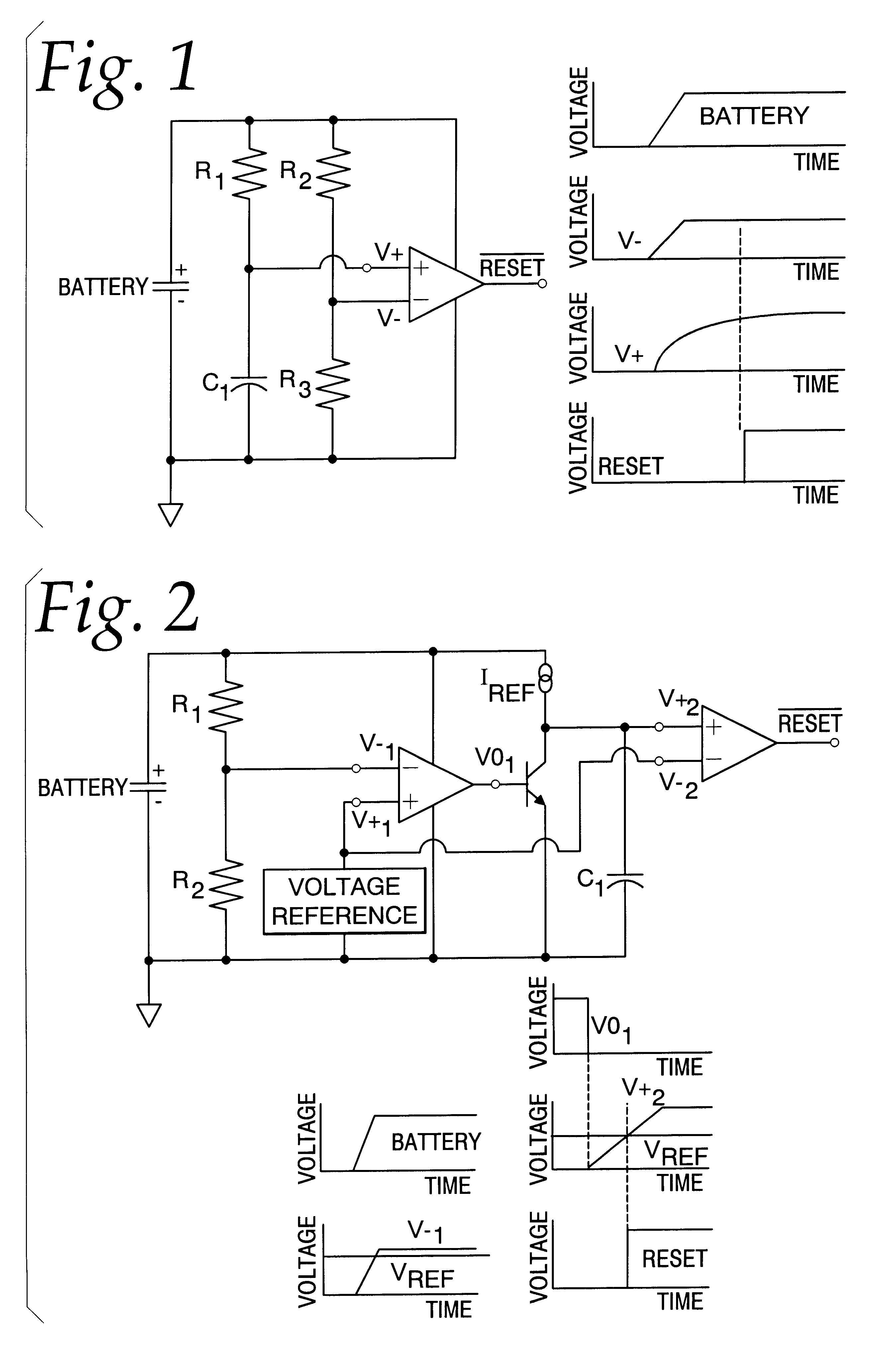
A disadvantage of the comparator POR circuit shown in FIG. 1 occurs when the battery supply voltage ramps up slowly.
A disadvantage of the dual-comparator POR circuit is the use of a voltage reference which must be operational during the power-up of the IC, or turned on before power-up of the IC to provide a voltage reference to the POR circuit.
Utilizing a voltage reference in a POR circuit in mobile electronic devices results in additional costs, power consumption and complexity.
Powering the voltage reference at all times results in increased power consumption.
In the alternative, repeatedly powering-up voltage reference accurately, internal or external to the IC, is difficult, inconvenient, and adds complexity to IC design.
Additionally, if implemented external to the IC, the voltage reference requires that a pin or pins be added to the IC, adding further complexity and size to the IC.
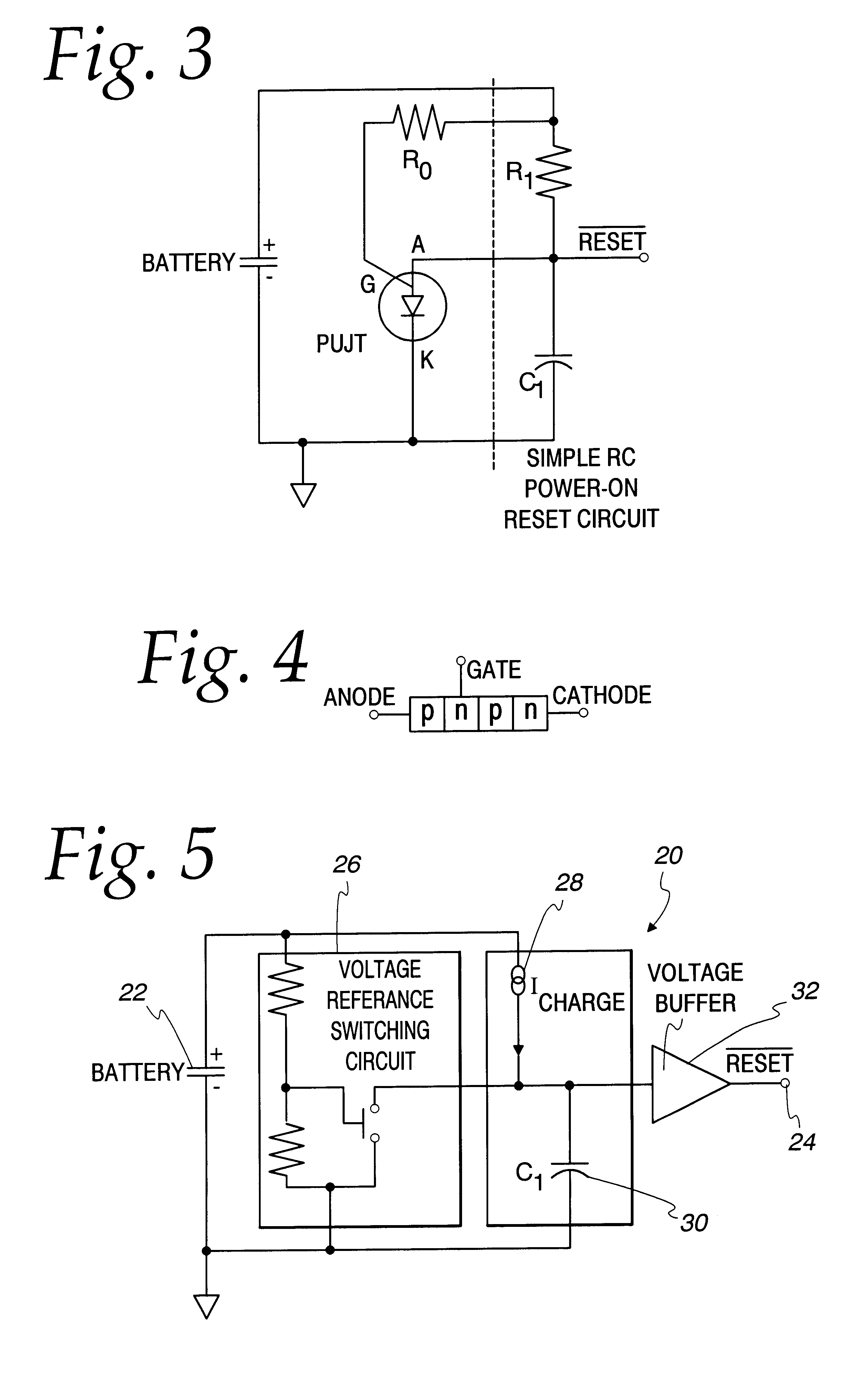
The first disadvantage of the RC POR circuit is that it requires a fast power-up and power down of the battery supply voltage.
Additionally, the RC POR circuit fails to provide accurate detection of a large supply voltage drop and does not provide the needed reset signal to prevent erratic operation of the IC.
The second disadvantage is that the RC components need to be so large that they may need to be implemented external to the IC.
Furthermore, PUJTs are not available in IC fabrication technology so the PUJT must be implemented external to the IC.

Method used


Image

  • Power-on reset circuit
  • Power-on reset circuit
  • Power-on reset circuit

Examples


Embodiment Construction

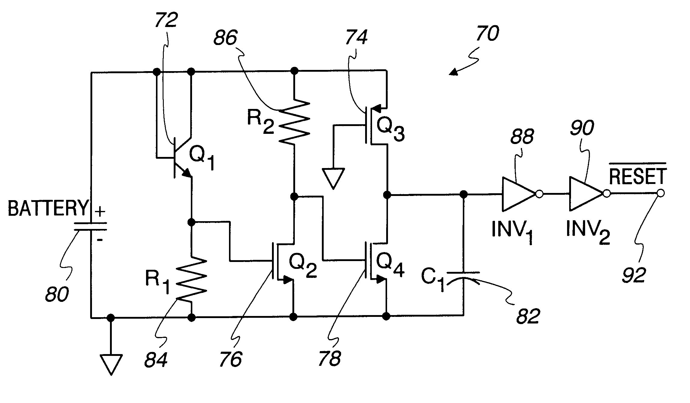
A preferred embodiment of the present invention comprises a POR circuit that will perform a reliable reset operation upon power-up of an IC under all conditions. Recognizing that the POR circuit is critical for proper IC operation, reliability of the POR circuit is paramount. Moreover, the POR circuit can be implemented either internal or external to the IC. The POR circuit generates a reset signal as long as the supply voltage is not in the operational range, to prevent undefined operations of the IC. The POR circuit also maintains the reset signal for a certain time after the supply voltage has returned to its nominal value, to ensure a proper reset of the IC.

The POR circuit also provides accurate detection of a serious supply voltage drop. The POR circuit achieves each of the above with low power consumption.

Since registers in an IC consist of flip-flops and latches, the preferred embodiment ensures that the supply voltage is always high enough during power-up to perform a reset ...


PUM


Abstract

A power-on reset circuit for resetting the register values contained on an integrated circuit upon power-up of the integrated circuit. The power-on reset circuit can be implemented either internal or external to the integrated circuit. The power-on reset circuit generates a reset signal as long as the supply voltage is not in the operational range and maintains the reset signal for a certain time after the supply voltage has returned to its nominal value. The power-on reset circuit also provides accurate detection of a serious supply voltage drop and has low power consumption. The power-on reset circuit comprises a battery, a voltage-referenced switching circuit, a current source, a capacitor and a voltage buffer.

Description

1. Field of the InventionThis invention relates generally to a power-on reset circuit used in electronic devices and particularly to a power-on reset circuit required upon the power-up of an integrated circuit to set the integrated circuit to a known and predefined state.2. Related ArtIntegrated circuit (IC) technology continues to advance, with ICs able to perform a greater number of increasingly complex functions. Consequently, the power consumption of ICs is increasing with the increasing complexity of the IC. Furthermore, there is a demand for longer battery life in mobile electronic systems, therefore, power consumption is a major concern in designing mobile electronic systems. Decreasing power consumption decreases cooling costs, power supply costs, packaging costs, and improves reliability. At times when an IC is not operating, the battery can be disconnected from the IC to disable operation of the chip, reducing power consumption.A concern in powering-up an IC after the batt...

Claims


Application Information

Patent Timeline
IPC IPC(8): H03K17/22
CPCH03K17/223
Inventor HOMOL, DAVID K.HOLDEN, ALAN R.KLEMMER, NIKOLAUSARPAIA, DOMENICO
Owner UNWIRED PLANET
Learn More