
Interlocked pipelined CMOS

a pipelined, logic circuit technology, applied in the direction of generating/distributing signals, instruments, program control, etc., can solve the problems of insufficient delay, insufficient delay, and circuit will not perform the intended function

Inactive Publication Date: 2001-01-30
IBM CORP
View PDF6 Cites 39 Cited by
  • Summary
  • Abstract
  • Description
  • Claims
  • Application Information

AI Technical Summary

Problems solved by technology

The major problem with this circuit, aside from speed issues for large fan-ins, is that all its inputs must overlap for both the "0" and "1" cases or there will be no change in the output state.
For complex interconnections of circuit blocks, commonly called macros, that have different speeds and interconnections this may not be the case and the circuit will not perform the intended function.
Aside from not dealing with how to solve the problem of multiple macros being interconnected, this approach is slow since the Acknowledge signal as shown in the wave forms is initiated when the output of the macro reaches a stable state.
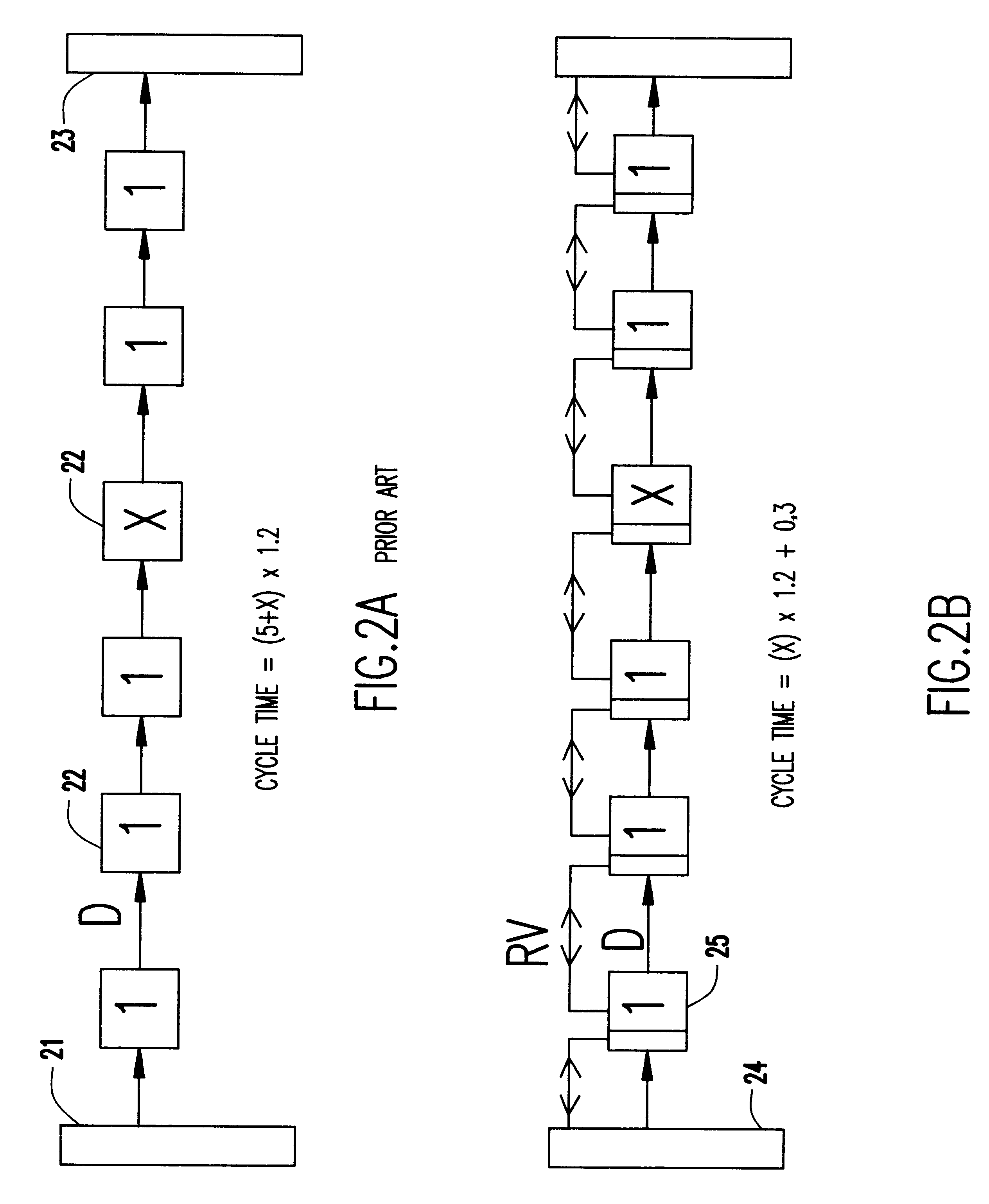
This means that after data is received, the macro must do its function before sending an acknowledgment which inserts additional delay in the cycle time.
This approach works well in a very regular environment such as one finds in memory, but is extremely difficult or impossible to implement in a more general environment without some kind of handshaking to guarantee reliable operation.
This pipelined operation results in an extremely fast cycle time.

Method used


Image

  • Interlocked pipelined CMOS
  • Interlocked pipelined CMOS
  • Interlocked pipelined CMOS

Examples


Embodiment Construction

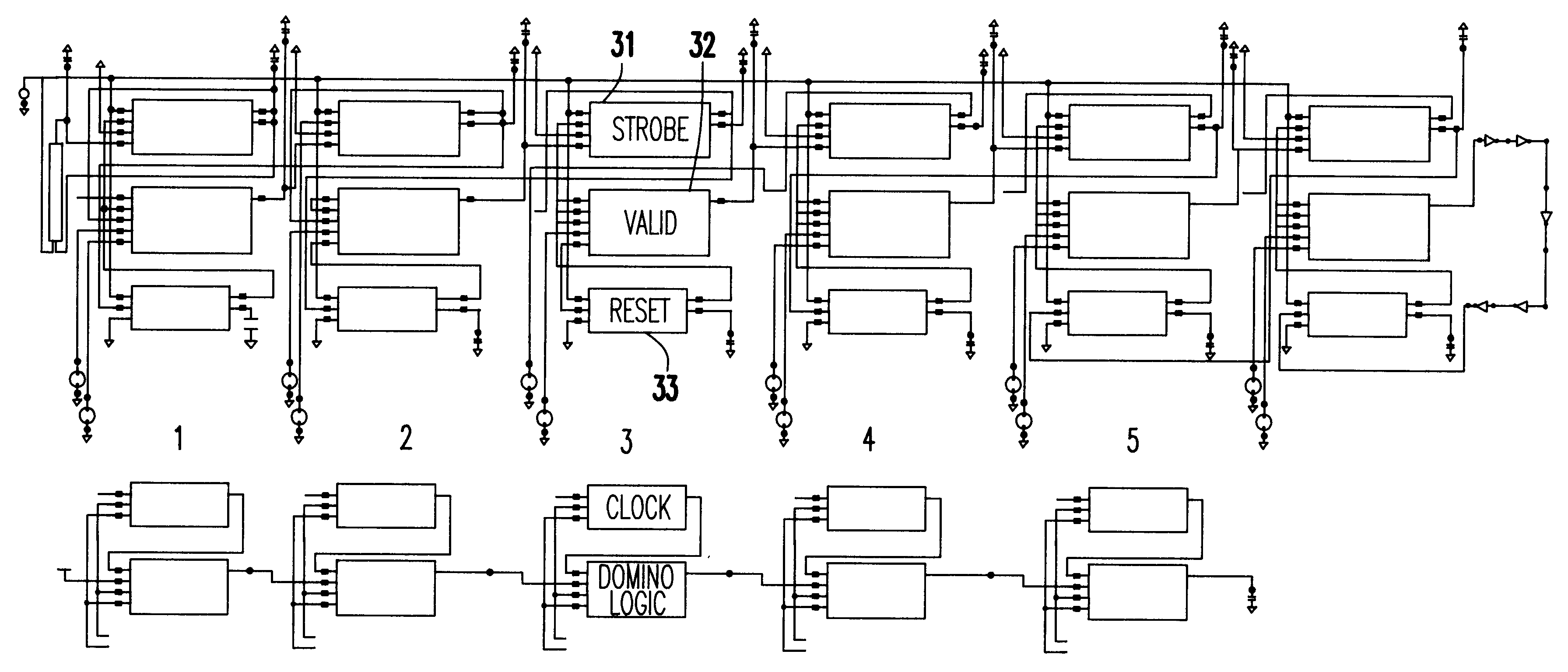
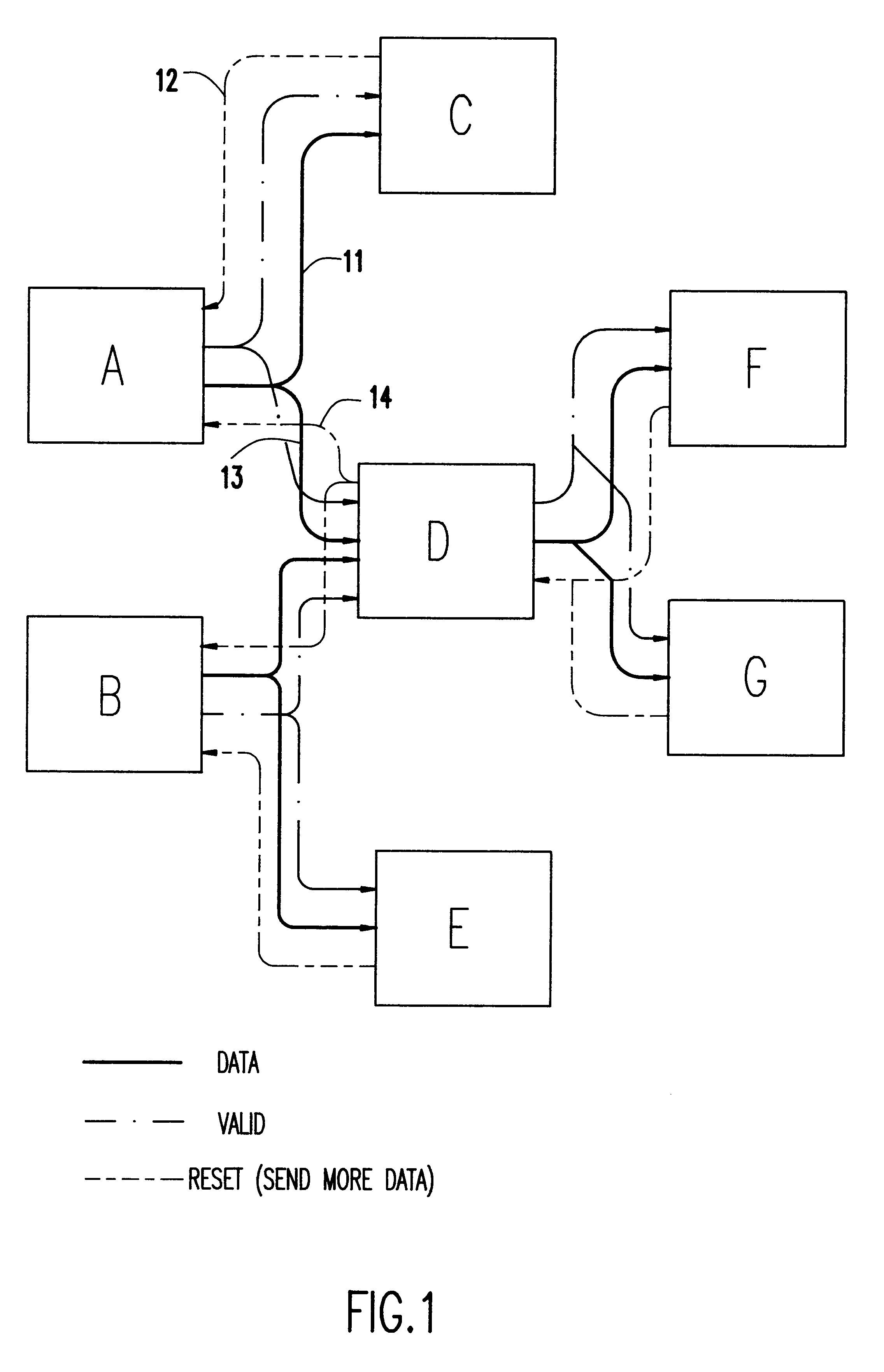
Referring now to the drawings, and more particularly to FIG. 1, there is shown a block diagram which, at the global macro level, is helpful in understanding how the interlocking and handshaking of the IPCMOS circuits according to the invention works. As shown in FIG. 1, between each of the macros, labeled A through G, that are transmitting and receiving data there are two additional signal lines. Between macros A and C, for example, these are a forward direction signal line 11 and a reverse direction signal line 12. Similarly, between macros A and D, these are a forward direction signal line 13 (which may be common with signal line 11) and a reverse direction signal line 14. In the forward direction, the additional signal from the transmitting macro signifies that the data coming from this macro has reached a valid state; whereas in the reverse direction the additional reset signal from the receiving macro signifies that the data has been received. Thus, there is handshaking or inte...


PUM


Abstract

An interlocked pipelined CMOS (IPCMOS) family of logic circuits provides extremely high performance pipelined operation and guarantees error free operation where variations in timing are compensated for automatically by the circuits. The IPCMOS logic circuits also provide a standard interface that makes it possible to interface different macro types easily. The IPCMOS logic circuits feature interlocking in both the forward and reverse directions. This "handshaking" guarantees error free timing and makes it possible to eliminate the need for a global clock at the macro level. Timing signals are generated locally at the macro level from the handshaking signals between macros. This makes it possible for the local circuits to deal with global timing variations caused by power supply noise, ACLV, and parameter variations. The macros operate in a pipelined mode with data advancing automatically from macro to macro with the timing controlled by the local handshaking signals. This pipelined operation results in an extremely fast cycle time. Another feature of IPCMOS is that the data inputs to a macro are only sampled when the data is in a valid state. making the concept of a standard macro interface possible. With this standard interface, different logic types such as static and dynamic circuits can be easily interconnected and the concept of reusable macros becomes a reality.

Description

1. Field of the InventionThe present invention generally relates to Complementary Metal Oxide Semiconductor (CMOS) Integrated Circuits (ICs) and, more particularly, to an Interlocked Pipelined CMOS (IPCMOS) family of logic circuits.2. Background DescriptionCircuit techniques are key to implementing the interlocked pipelined approach. In order for the approach to be viable, the circuit techniques must be extremely fast, simple, reliable , and very efficient. The general concepts of handshaking or interlocking and pipelining and asynchronous self-timing are not new and have all been proposed in a variety of forms for systems.The Muller C-element described by Carver Mead and Lynn Conway in Chapter 7 of Introduction to VLSI Systems, published by Addison-Wesley Publishing Company Inc. (1980), and shown in FIG. 18 is a bistable device whose output becomes a "1" only after all of its inputs are "1" and whose output becomes a "0" only after all of its inputs are "0". The major problem with ...

Claims


Application Information

Patent Timeline
Patent Type & Authority Patents(United States)
IPC IPC(8): G06F9/38
CPCG06F9/3869
Inventor SCHUSTER, STANLEY EVERETTCOOK, PETER WILLIAM
Owner IBM CORP
Learn More