
Gravimetric blender with operatively coupled bar code reader

a gravimetric blender and bar code reader technology, applied in the direction of process and machine control, electric programme control, program control, etc., can solve the problems of not requiring additional coloration, defective product, and liquid color material cannot be pre-blended into one of the solid material components and stored,

Inactive Publication Date: 2001-02-13
MAGUIRE PROD
View PDF55 Cites 76 Cited by
  • Summary
  • Abstract
  • Description
  • Claims
  • Application Information

AI Technical Summary

Benefits of technology

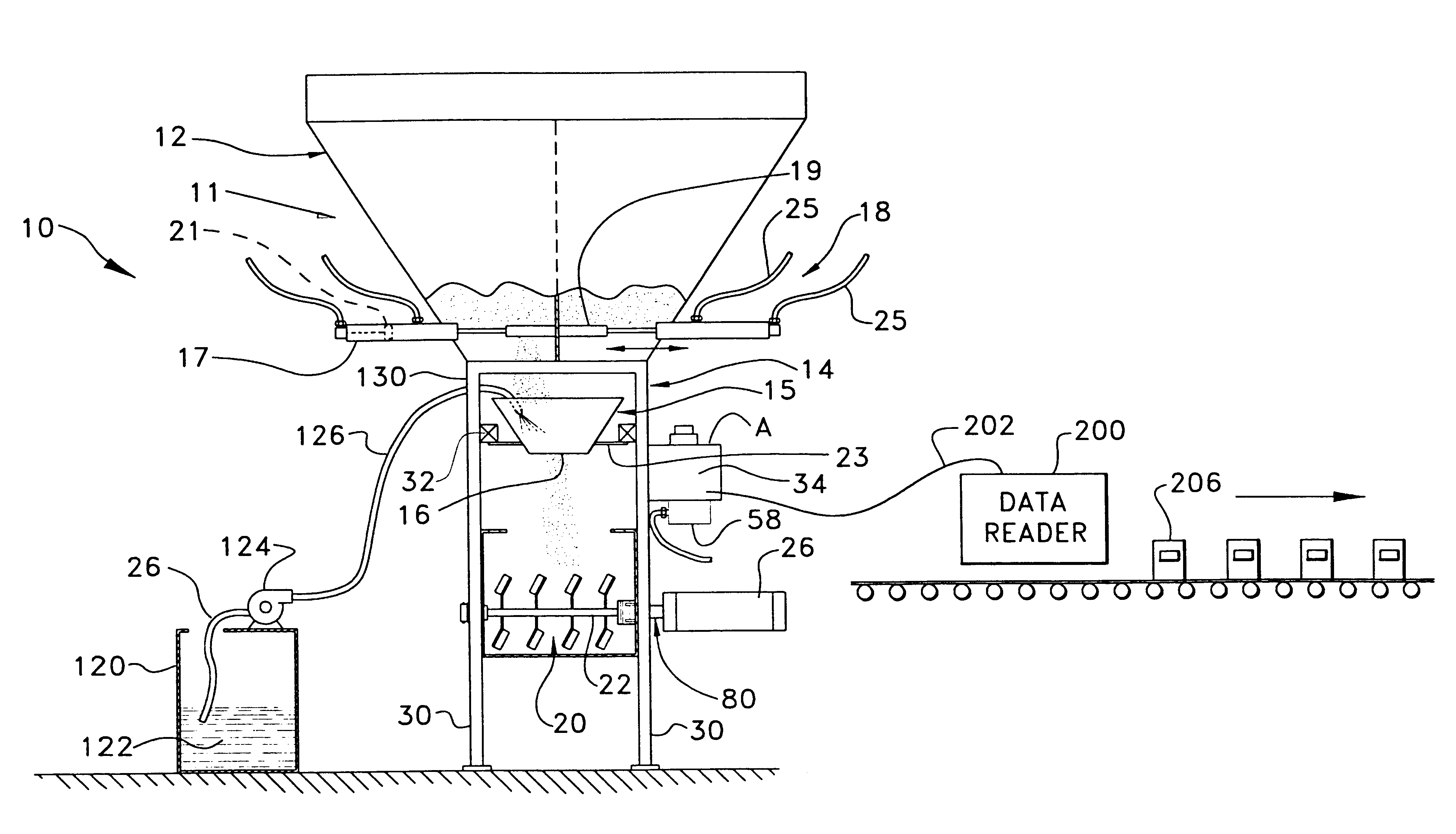
Gravimetric blending using a gravimetric blender of the type to which this invention relates permits detection of the presence of colored solid regrind material and resultant adjustment of the amount of liquid color being added. This invention, in one of its aspects combining a liquid color supply pump, a gravimetric blender and a command and / or data code reader results in addition of liquid color to the material blend in a heretofore unknown, controlled and optimized manner, providing many of the same advantages as when blending just dry plastic powder and concentrated plastic resin pellets.
When these granular solid and liquid materials are added to the gravimetric blender there is precise metering, no over-coloring and no danger of recoloring regrind material.
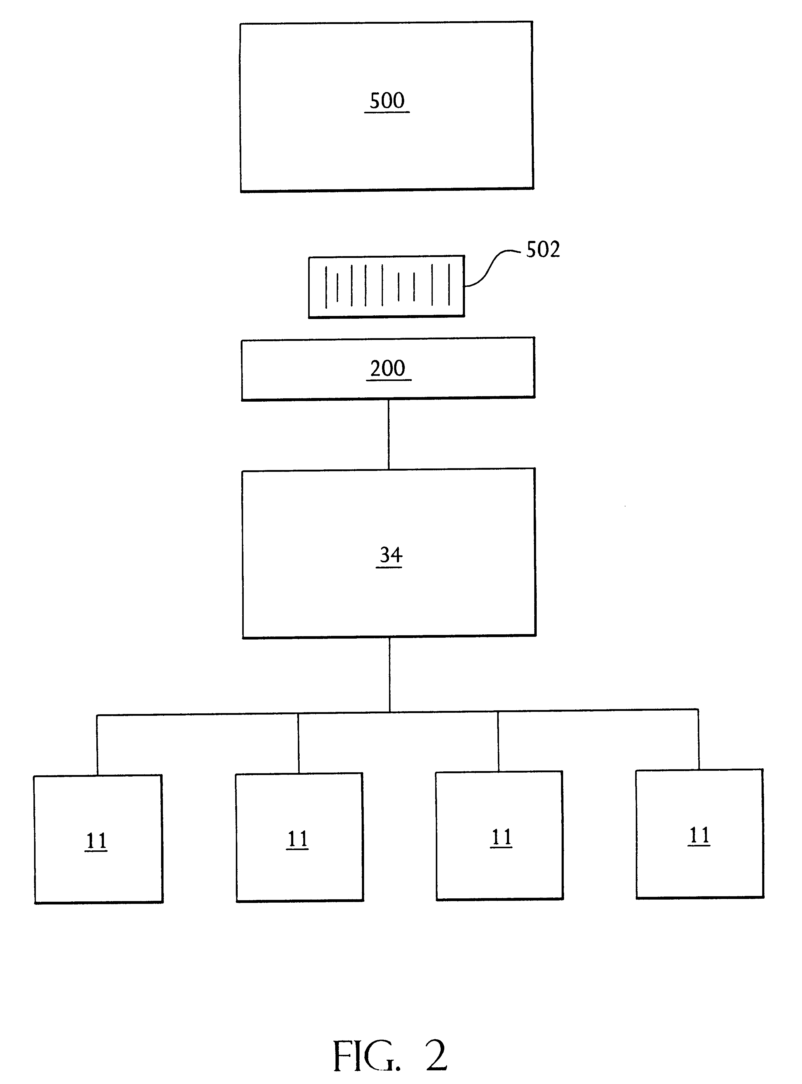
Desirably, the command and / or data reader provides one or more lines of information directly into a memory component of a gravimetric blender controller or microprocessor. This permits set-up information for operation of the gravimetric blender to be entered easily and accurately, either by the operator manually entering such information into the gravimetric blender microprocessor, or automatically with the information being scanned by the reader from a label or a container located on a moving conveyor belt or elsewhere. This also permits operation of the blender to be changed dynamically by providing new and updated commands to the microprocessor controlling operation of the blender. Such supplying of commands on a dynamic basis reduces the usage of microprocessor memory thereby providing additional memory for storage of data, permitting more sophisticated algorithms to be executed and the like.
In still yet another one of the aspects of this invention, by providing the set-up information in a bar code or other machine readable media on a container or elsewhere and placing the container or other bar code labels or other machine readable media on a conveyor, the compatible reader can read those data and supply the information to the gravimetric blender thereby permitting the gravimetric blender to automatically fill the containers with the requested blend of plastic resin material at the required weight for proper and accurate manufacture of the plastic part of interest.

Problems solved by technology

One of these may be "regrind", consisting of ground plastic resin which had previously been molded or extruded and which either resulted in a defective product or was excess material not formed into a desired product.
However, when color amounts are too high, the problem is not visible and operators manually operating the process normally do not make any adjustment in the amount of color.
Liquid color material cannot be pre-blended into one of the solid material components and stored because of the danger inherent and difficulties attendant to clean-up in the event of component failure.
This approach creates difficulties, among them being compensating for addition of pre-colored regrind solid material to the material mix.
Hence, the presence of already colored regrind, not requiring additional coloration, cannot be detected.
As a result, excess liquid color is typically added to the blend, sometimes producing an unacceptable product and always resulting in the use of unneeded color material, which is undesirable and results in unnecessary expense.
Vibrational and shock loading of the load cells may result in erroneous measurements of the weight of the weigh bin and the material contained therein.
These erroneous measurements may result in addition of excess material or an insufficient amount of a material component in a subsequent batch thereby producing a batch of blended material deviating from the desired specifications.
The load cells are subject to some vibration and shock loading due to the presence of pneumatic piston-cylinder combinations typically connected to the frame of the gravimetric blender and used to dispense solid granular resinous material from a hopper downwardly into the weigh bin.
Further, vibrational and shock loading of the load cells may result from use of typically pneumatically driven piston-cylinder combinations to empty the weigh bin when the weight measurement is complete.
Yet further vibrational and shock loading of the load cells may result from operation of the mixing chamber and the motor driving mixing means within the mixing chamber.
When the gravimetric blender is mounted directly on a plastics material processing machine such as an extruder or, more particularly, an injection molding machine, the load cells of the gravimetric blender can be subjected to very substantial shock and vibrational loading.
There is a considerable amount of movement in an injection molding machine and the parts which move are heavy.
In gravimetric blenders utilizing single load cells, loads on a cell may be substantial.
Hence vibrational loading of the frame of the gravimetric blender may produce substantial vibrational loading of the load cell with stress to the load cell due to the weight carried by the load cell.
Cantilevering the weigh bin from the load cell results in high moments of inertia being applied to the load cell when the load cell is subject to vibration and shock loading.
One disadvantage attendant to gravimetric blenders is that while these blenders are operated and controlled by microprocessors, data is input into the microprocessor manually.
Additionally, it has not been known heretofore to provide commands from a remote locale to a microprocessor controlling one of more gravimetric blenders on a dynamic basis for alteration of the operational profile of the microprocessor and hence the gravimetric blender.

Method used


Image

  • Gravimetric blender with operatively coupled bar code reader
  • Gravimetric blender with operatively coupled bar code reader
  • Gravimetric blender with operatively coupled bar code reader

Examples


Embodiment Construction

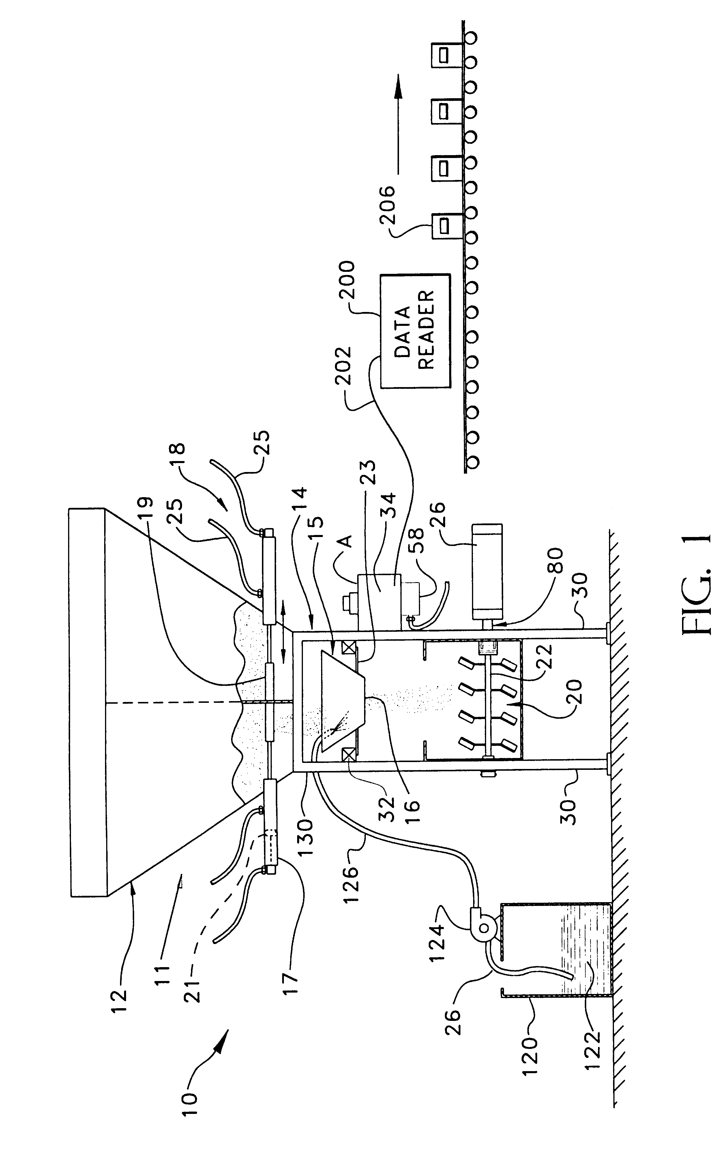
Referring to the drawings and to FIG. 1 in particular, a gravimetric blender together with an optional color addition pump and an optical or magnetic reader or bar code command and / or data reader combination is illustrated with this combination being indicated generally 10.

In the context of this invention, it is to be understood that reference to optical or magnetic "character" readers is not to be construed as being limited readers which recognize alphanumeric character data to the exclusion of readers which recognize binary characters. Both binary and alphanumeric character command and / or data readers are encompassed within the term "character reader" as used herein.

The gravimetric blender is designated generally 11 and includes a hopper, designated generally 12, supported by a frame designated generally 14 which holds a weigh bin 15 into which portions of plastic resin material, and optionally liquid color material, can be metered and weighed prior to release into a mix chamber 2...


PUM

PropertyMeasurementUnit
pressuresaaaaaaaaaa
suction pressureaaaaaaaaaa
weightaaaaaaaaaa

Abstract

A method for weight blending of granular materials comprises at a remote site generating a command for desired operation of granular material weight blending apparatus; encoding said command into transportable time-stable machine readable tangible storage media; transporting said media to a bar code reader operatively connected to said granular material weight blending apparatus; scanning the tangible media having the command encoded thereon to read the command; and providing the read command as input to a in microprocessor operatively connected to said granular material weight blending apparatus for regulating operation of the same.

Description

This invention relates generally to automated management, control and optimization of methods and apparatus for providing or otherwise processing precisely measured amounts of granular materials and, optionally, precisely measured amounts of coloring agent(s), particularly pigment in liquid form, preparatory to further processing of the combined granular materials and, optionally, liquid coloring agent(s). The invention relates more specifically to automated management, control and optimization of gravimetric blenders, optionally in combination with color addition pumps, providing precisely measured amounts of plastic resin material, and, optionally liquid coloring agents, and mixing these components prior to supplying the blended mixture to plastics manufacturing and processing equipment such as plastic injection molding, compression molding and extrusion equipment.FIELD OF THE INVENTION AND DESCRIPTION OF THE PRIOR ARTThe modern gravimetric blender was essentially originated by on...

Claims


Application Information

Patent Timeline
Patent Type & Authority Patents(United States)
IPC IPC(8): B01F15/04B01F15/00B01F3/00B01F3/18B29B7/30B29B7/60G05D11/00G05D11/13B01F3/12B01F7/00B01F7/02
CPCB01F3/18B01F15/00253B01F15/00318B01F15/0445B29B7/603G05D11/132G05D11/133G05D11/134B01F7/02B01F2003/1257B01F7/0025B29B7/244B29B7/283B29B7/94B29B7/78B29B7/582B29B7/728B29B7/7461B01F23/565B01F23/60B01F27/112B01F27/60B01F35/2207B01F35/2209B01F35/881
Inventor MAGUIRE, STEPHEN B.MAGUIRE, PAUL S.
Owner MAGUIRE PROD
Learn More